Bogie shaft end column type permanent magnet power generation device

A technology of permanent magnet power generation and bogie shaft, which is applied in the direction of electromechanical devices, circuit devices, battery circuit devices, etc., can solve the problems of increasing the mass between the springs of the motor, the motor can not be symmetrical, and the shaft is designed separately, so as to achieve low production cost, The effect of small axial size and strong practicability

Inactive Publication Date: 2021-03-19
CHANGSHA UNIVERSITY OF SCIENCE AND TECHNOLOGY
View PDF1 Cites 0 Cited by
  • Summary
  • Abstract
  • Description
  • Claims
  • Application Information

AI Technical Summary

Problems solved by technology

[0003] In the prior art, the power generation device installed on the bogie needs to be arranged separately on the bogie, and the belt drive is used, so the bogie shaft needs to be designed separately; since the motor cannot be centrally symmetrical on the bogie, it is difficult to match its dynamic parameters
At the same time, due to the increase of the sprung mass of the motor, the dynamic performance of the bogie will become worse
Moreover, the bogie with the power generation device on the bogie is generally a passenger car bogie, and its frame is an integral structure that can be fixed and installed; The bogie power generation unit cannot be installed
[0004] The patent "Axle End Disc Permanent Magnet Generating Device for Railway Freight Cars (Patent No.: 201210561240.X)" installs the generating device on the axle of the train, which solves the problem that the generating device occupies a large space on the bogie, the shaft is designed separately, and the steering of the truck However, the device covers the stator structure and rotor structure inside the axle box end cover, and is fixedly connected with the axle box bearing seat sleeved on the axle through the axle box end cover. For the installation basis, this structure makes the axle box bearing seat, stator structure, rotor structure and axle diameter need to be used together

Method used


Image

  • Bogie shaft end column type permanent magnet power generation device
  • Bogie shaft end column type permanent magnet power generation device
  • Bogie shaft end column type permanent magnet power generation device

Examples


Embodiment Construction

[0020] The present invention will be described in further detail below in conjunction with accompanying drawing and specific embodiment, obviously, described embodiment is only a part of embodiment of the present invention, rather than all embodiment, based on the embodiment in the present invention, those skilled in the art All other embodiments obtained by personnel without creative work belong to the protection scope of the present invention.

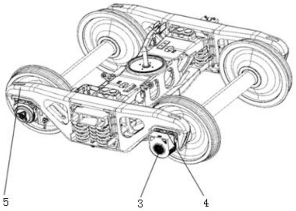
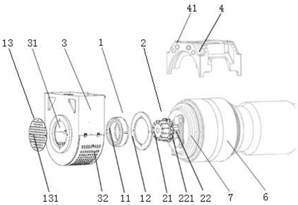
[0021] Such as figure 1 , figure 2 As shown, the bogie shaft end column type permanent magnet generator of this embodiment includes a stator assembly 1, a rotor assembly 2, a machine cover 3 and a bearing saddle 4, and the bearing saddle 4 is fixed on the bogie 5, and the The rotor assembly 2 is installed on the outer end surface of the shaft end cover 7 of the rotating shaft 6 and rotates concentrically with the rotating shaft 6. The stator assembly 1 is installed on the machine cover 3, and the machine cover 3 is installed on the...


PUM


Abstract

The invention relates to a bogie shaft end column type permanent magnet power generation device. The device comprises a stator assembly, a rotor assembly, a hood and a bearing saddle, wherein the bearing saddle is fixedly installed on a bogie, the rotor assembly is installed on the end face of a shaft end cover of a rotating shaft and concentrically rotates along with the rotating shaft, the stator assembly is installed on the hood, and the hood is installed on the bearing saddle; the stator assembly and the rotor assembly are mutually sleeved and form a radial gap. The device has advantages of being small in axial size, small in size, low in production cost, high in reliability, easy to maintain, high in practicability, capable of not changing the original internal structure of the axle and the like, and a purpose of converting mechanical energy into electric energy is achieved; the hood provided with the electromagnetic coils does not take a rotating shaft as an installation basis, and the sizes of the permanent magnets and the corresponding electromagnetic coils can be increased in a certain space according to the requirement for electric energy; the heat dissipation structure is arranged in the power generation device, heat energy generated in the power generation process is dissipated in time, and the situation that the power generation effect is affected due to too high heat is avoided.

Description

technical field [0001] The invention relates to the technical field of railway vehicle power generation, in particular to a bogie axle end column type permanent magnet power generation device. Background technique [0002] The speed of rail trains is constantly breaking through, and the resulting energy consumption is also increasing. In order to ensure the stable operation of the train, meet the overall power supply needs of the train, make full use of the kinetic energy of the train, and improve transportation efficiency, a reasonable and practical steering is designed. It is of great significance to support the shaft end power generation device. [0003] In the prior art, the power generation device installed on the bogie needs to be arranged separately on the bogie, and the belt drive is adopted, so the bogie shaft needs to be designed separately; since the motor cannot be centrally symmetrical on the bogie, it is difficult to match its dynamic parameters. At the same t...

Claims


Application Information

Patent Timeline
Patent Type & Authority Applications(China)
IPC IPC(8): H02K21/24H02K1/27H02K1/18H02K9/06H02J7/14
CPCH02J7/14H02K1/182H02K1/2793H02K9/06H02K21/24
Inventor 苗秀娟孙国营昝壮
Owner CHANGSHA UNIVERSITY OF SCIENCE AND TECHNOLOGY
Why Eureka
Try Eureka