Equipment for forming arc steel bars for municipal well lid pouring in batch
A technology for forming equipment and manhole covers, which is applied in the field of batch forming equipment for circular arc steel bars for municipal manhole cover pouring. It can solve the problems of low production efficiency of arc steel bars and the inability to automatically unload and discharge materials, so as to improve equipment safety and speed. , the effect of convenient transportation
- Summary
- Abstract
- Description
- Claims
- Application Information
AI Technical Summary
Problems solved by technology
Method used
Image

Examples
Embodiment 1
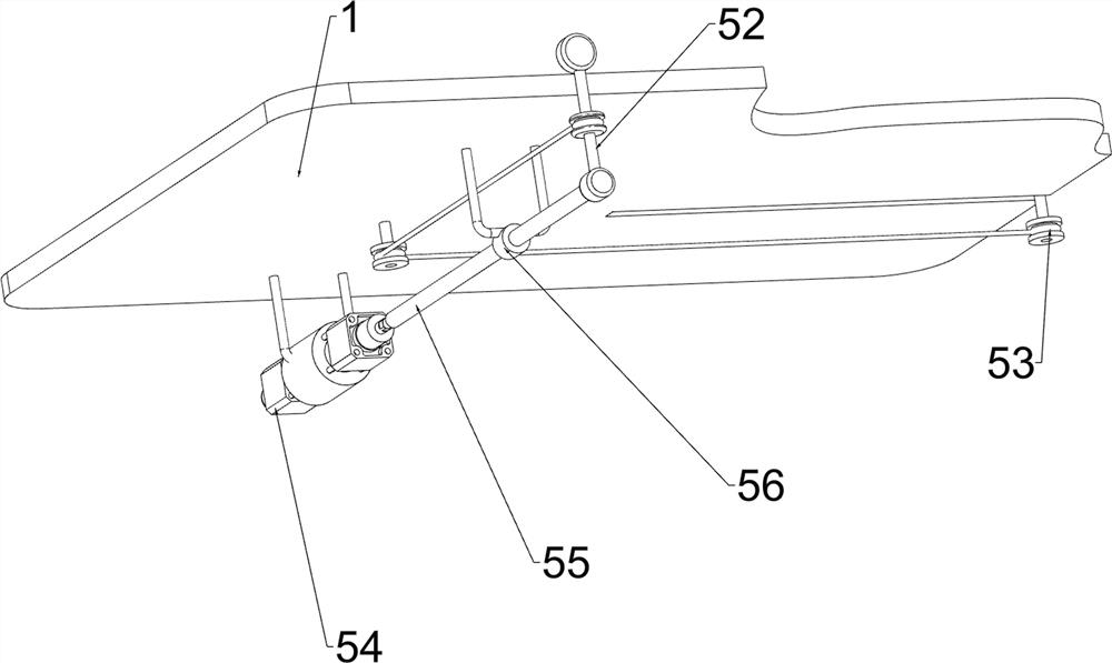
[0066] A batch forming equipment for circular arc steel bars for municipal manhole cover pouring, such as figure 1As shown, it includes a first fixed plate 1, a guide rail 2, a third fixed plate 3, a pushing mechanism 4 and an extruding mechanism 5. Two guide rails 2 are arranged on the left side of the top of the first fixed plate 1, and the first fixed plate 1 A third fixed plate 3 is provided on the left side of the top, and the third fixed plate 3 is located on the left side of the guide rail 2. The right part of the first fixed plate 1 is provided with a pushing mechanism 4, and the left part of the first fixed plate 1 is provided with an extrusion mechanism 5. The extruding mechanism 5 cooperates with the pushing mechanism 4 and the guide rail 2 .
[0067] When manually shaping the steel bars, more manpower is needed and the speed is relatively slow. The present invention helps people improve the efficiency of steel bar shaping work. First, the steel bars can be placed i...
Embodiment 2
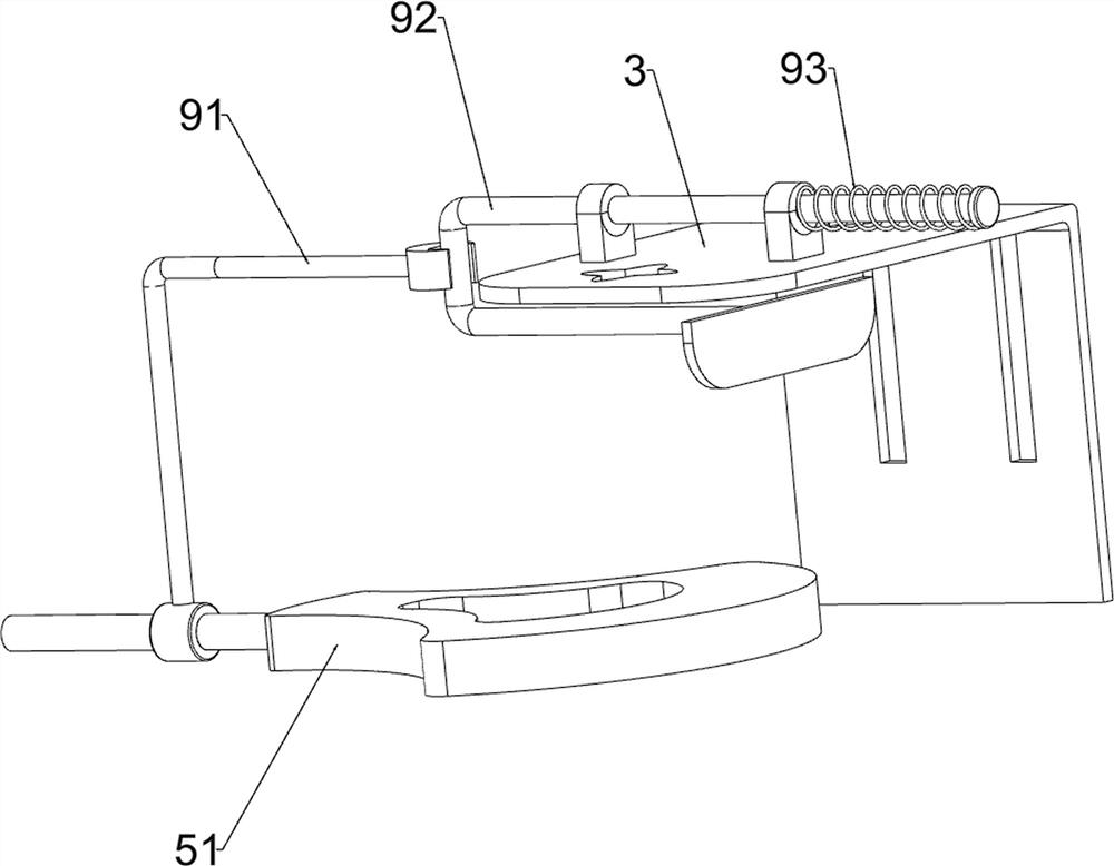
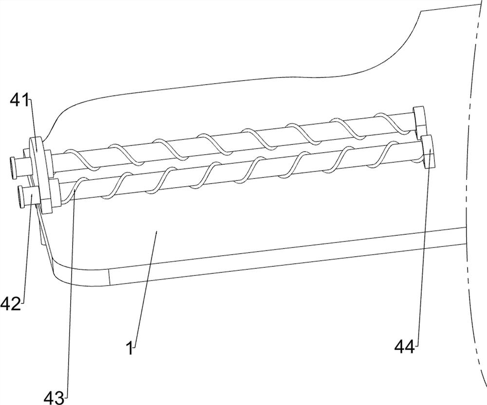
[0069] On the basis of Example 1, such as figure 2 , image 3 and Figure 4 As shown, the pushing mechanism 4 includes a first push plate 41, a first rod 42, a first spring 43 and a first fixed rod 44, and the middle part of the top side of the first fixed plate 1 is provided with two first fixed rods 44, The right side of the first fixed rod 44 is provided with a first rod 42, and the right part of the two first rods 42 is slidably provided with a first push plate 41, and the first push plate 41 cooperates with the first fixed plate 1, and the first rod A first spring 43 is wound around the member 42 , and the first spring 43 is connected with the first fixing rod 44 and the first push plate 41 .
[0070] First place the steel bar to be reshaped between the two first rods 42, manually push the first push plate 41 to the left, the first spring 43 is compressed, and after the first push plate 41 cooperates with the steel bar, the first push plate 41 pushes The steel bar mov...
Embodiment 3
[0074] On the basis of Example 2, such as figure 1 , Figure 5 , Figure 6 , Figure 7 and Figure 8 As shown, it also includes a blanking mechanism 6. The right part of the first fixed plate 1 is provided with a blanking mechanism 6. The blanking mechanism 6 includes a fourth fixed plate 61, a blanking part 62, a second push plate 63, a first L-shaped bar 65 and the second spring 66, the first fixed plate 1 top side right part is provided with two the 4th fixed plate 61, and the first fixed plate 1 right side sliding type is provided with two blanking parts 62, and the blanking part 62 cooperates with the fourth fixed plate 61, and the outer side of the blanking part 62 is connected with a second push plate 63, and the right part of the top side of the first fixed plate 1 is provided with two first L-shaped bars 65, and the first L-shaped bar 65 is connected with the first L-shaped bar 65. The two push plates 63 are slidably connected, and a second spring 66 is wound on t...
PUM
 Abstract
Description
Claims
Application Information
 - R&D
- Intellectual Property
- Life Sciences
- Materials
- Tech Scout
- Unparalleled Data Quality
- Higher Quality Content
- 60% Fewer Hallucinations
Browse by: Latest US Patents, China's latest patents, Technical Efficacy Thesaurus, Application Domain, Technology Topic, Popular Technical Reports.
© 2025 PatSnap. All rights reserved.Legal|Privacy policy|Modern Slavery Act Transparency Statement|Sitemap|About US| Contact US: help@patsnap.com