Supercharge Your Innovation With Domain-Expert AI Agents!

Horizontal punching device

A drilling device, horizontal technology, applied in the direction of transportation and packaging, boring/drilling, drilling/drilling equipment, etc., can solve the problems of impact on the life of the drilling machine, slow drilling speed, etc., and achieve convenient centering , fast cutting and reaming, and convenient discharge

Pending Publication Date: 2021-06-11
宁波恺露重型锻造有限公司
View PDF0 Cites 0 Cited by
  • Summary
  • Abstract
  • Description
  • Claims
  • Application Information

AI Technical Summary

Problems solved by technology

[0004] The drilling speed of this kind of drilling method is slow, and workers need to be arranged on the drilling machine to carry out chip removal operations every day. Because the rotary table needs to stop when the chips are removed, and the motor starts repeatedly, the life of the drilling machine is also affected.

Method used


Image

  • Horizontal punching device
  • Horizontal punching device
  • Horizontal punching device

Examples


Embodiment 1

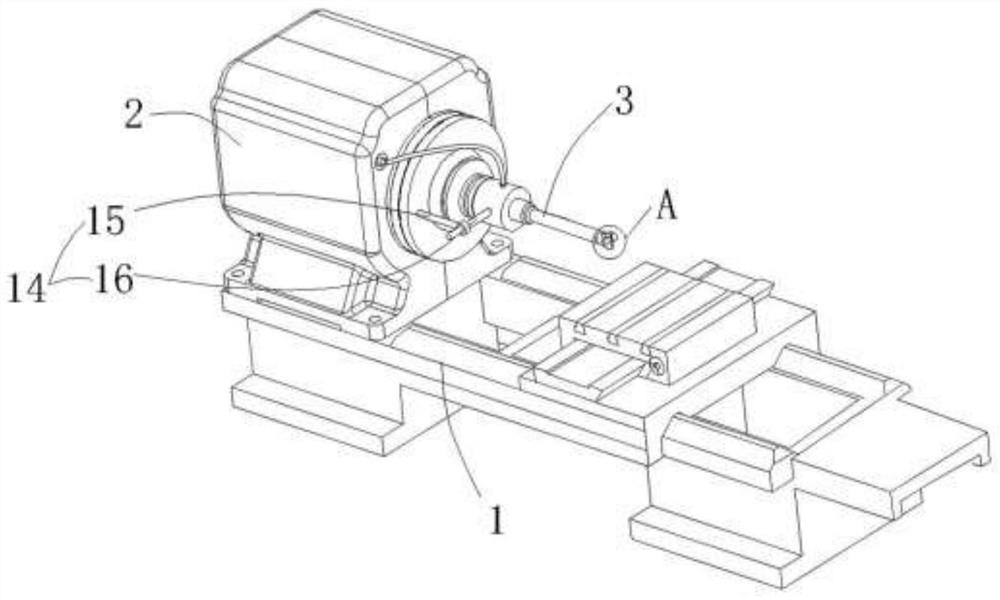
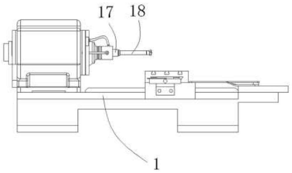
[0027] combined with Figures 1 to 5 , a horizontal punching device, comprising a horizontal body 1, a spindle box 2 is provided on one side of the horizontal body 1, a motor and a motor connected to the output shaft of the motor are arranged in the spindle box 2 Speed ​​reduction mechanism, the output shaft outer end of the speed reduction mechanism stretches out on the right side of the main shaft box 2, the right side of the main shaft box 2 is connected with a drill rod 3 arranged transversely, and the head of the drill rod 3 is provided with a drill bit Group 4, the drill bit group 4 includes a drill bit 5 in the center and edge edges 6 on both sides, the edge edge 6 is provided with a cutting blade 7;

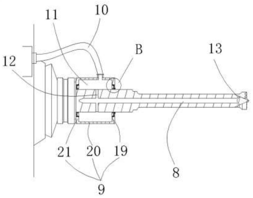
[0028] The drill pipe 3 is provided with a cooling passage 8, and the rear side of the drill pipe 3 is provided with an infusion sleeve 9, and the infusion sleeve 9 is connected to the liquid inlet pipe 10, and the infusion sleeve 9 is fixed on the headstock 2, so that T...


PUM


Abstract

The invention relates to a horizontal punching device which comprises a horizontal machine body. A spindle box is arranged on one side of the horizontal machine body, the outer end of an output shaft extends out of the right side of the spindle box, a transversely-arranged drill rod is connected to the right side of the spindle box, and a drill bit set is arranged at the head of the drill rod. The drill bit set comprises a drill bit located at the center and cutting edges on the two sides, and cutting blades are arranged on the cutting edges. A cooling channel is formed in the drill rod, a liquid conveying sleeve is arranged on the rear side of the drill rod, the liquid conveying sleeve is communicated with a liquid inlet pipe and fixed to the spindle box, the drill rod can rotate in the liquid conveying sleeve, a liquid conveying cavity is formed between the liquid conveying sleeve and the drill rod, and a liquid inlet channel communicating with the liquid conveying cavity and the cooling channel is formed in the drill rod. The head of the drill rod is provided with a liquid outlet channel communicating with the cooling channel. The horizontal punching device has the beneficial effects that by using the transverse drilling mode, the situation that scrap iron is accumulated in a drilled hole due to gravity and cannot be discharged is avoided, and therefore the scrap iron can be removed without multi-stage drilling and scrap drawing-out.

Description

technical field [0001] The invention relates to a punching device. Background technique [0002] When a common vertical drilling machine is used to process a workpiece with a large inner diameter, it is easy to have difficulty in chip removal, resulting in the jamming of the drill bit. [0003] Generally, to deal with this situation, we need to use multiple drilling methods to drill holes, and use manual chip removal between each drilling, and then carry out the next deepening. [0004] The drilling speed of this kind of drilling method is slow, and workers need to be arranged on the drilling machine to remove chips every day. Because when removing chips, the turntable needs to stop, and the motor starts repeatedly, and the life of the drilling machine is also affected. Contents of the invention [0005] In order to overcome the deficiency of the slow speed of the current horizontal punching device, the present invention provides a horizontal punching device with a fast p...

Claims


Application Information

Patent Timeline
Patent Type & Authority Applications(China)
IPC IPC(8): B23B39/00B23B47/34B23B51/06B23B51/08B23Q11/10
CPCB23B51/08B23B51/06B23B39/00B23Q11/10B23B47/34
Inventor 戎明忠童爱平
Owner 宁波恺露重型锻造有限公司
Features
  • R&D
  • Intellectual Property
  • Life Sciences
  • Materials
  • Tech Scout
  • Unparalleled Data Quality
  • Higher Quality Content
  • 60% Fewer Hallucinations
Learn More