
Planer type milling machine

A technology of gantry milling machine and worktable, applied in the field of milling machines, can solve the problems of low production efficiency and high production cost, and achieve the effects of improving production efficiency, reducing production cost and reducing labor usage.

Pending Publication Date: 2021-06-11
东莞市固达机械制造有限公司
View PDF7 Cites 0 Cited by
  • Summary
  • Abstract
  • Description
  • Claims
  • Application Information

AI Technical Summary

Problems solved by technology

[0003] In order to overcome the disadvantages of low production efficiency and high production cost in the prior art that the gantry rotation needs manual assistance, the purpose of the present invention is to provide a gantry milling machine, which can realize the automatic rotation of the gantry, improve production efficiency, and reduce production costs. cost

Method used


Image

  • Planer type milling machine
  • Planer type milling machine
  • Planer type milling machine

Examples


Embodiment Construction

[0046] In order to facilitate the understanding of those skilled in the art, the present invention will be further described below in conjunction with the embodiments and accompanying drawings, and the contents mentioned in the implementation modes are not intended to limit the present invention.

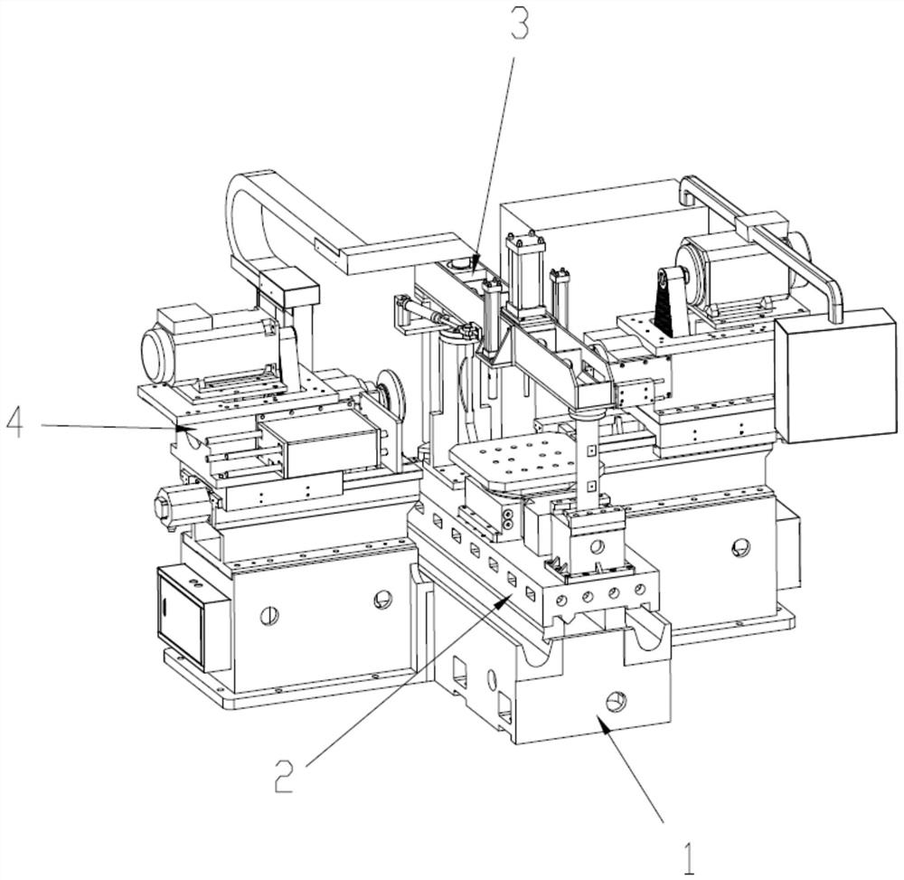
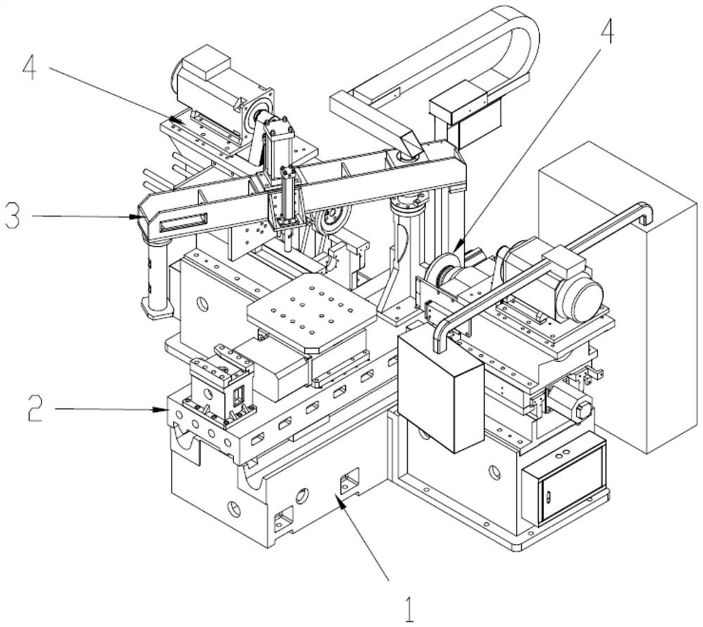
[0047] see Figure 1 to Figure 11 , a gantry milling machine of the present invention, comprising a base 1, a workbench 2, an automatic opening and closing gantry 3 and a tool processing device 4;

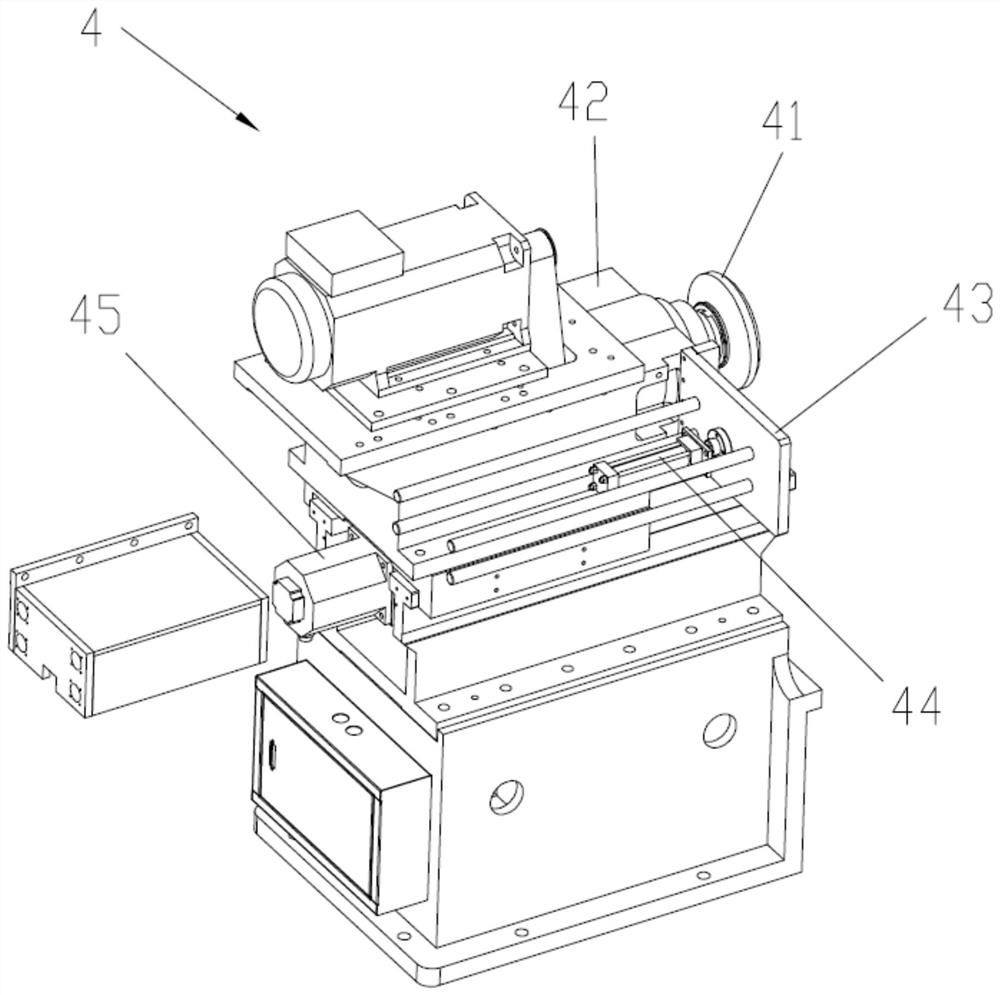
[0048] The workbench 2 is set on the base 1, the automatic opening and closing gantry 3 is set on the workbench 2, the tool processing device 4 is arranged close to the base 1, the tool processing device 4 is provided with a tool chuck 41, the The tool chuck 41 reciprocates toward the direction of the workbench 2;

[0049] The automatic opening and closing gantry 3 includes a seat body 31, a crossbeam 32, a crossbeam drive assembly 33, an induction element 34 and a pressing device 35, t...


PUM


Abstract

The invention relates to the technical field of milling machines, in particular to a planer type milling machine. The machine comprises a base, a workbench arranged on the base, an automatic opening and closing portal frame arranged on the workbench and a cutter machining device; the automatic opening and closing portal frame comprises a seat body arranged on the workbench, a cross beam rotationally connected to the seat body, a cross beam driving assembly used for driving the cross beam to rotate, an induction piece arranged on the cross beam driving assembly and a jacking device arranged on the cross beam, the cross beam driving assembly comprises a first driving source, a piston rod and a shell, the shell is arranged on the seat body, the first driving source is contained in the shell and drives the piston rod to stretch out and draw back, and the piston rod is fixedly connected with the cross beam; the induction piece is arranged in the shell and used for inducting the piston rod; and the automatic opening and closing portal frame is arranged on the workbench of the milling machine, the automatic opening and closing portal frame comprises the cross beam driving assembly and the induction piece, the purpose that the cross beam driving assembly drives the cross beam to rotate automatically is achieved, the labor use amount is reduced, the production efficiency is improved, and the production cost is reduced.

Description

technical field [0001] The invention relates to the technical field of milling machines, in particular to a gantry milling machine. Background technique [0002] The existing milling machine includes a workbench for placing materials, a gantry for pressing materials, and a tool holder for installing tools. Working status: the gantry is set above the workbench and holds materials. When replacing materials , move the gantry to increase the space above the workbench, which is beneficial for the manipulator to pick up and replace materials, but the existing gantry structure needs to be manually pushed to make the gantry leave the top of the workbench. This manual operation method reduces Production efficiency, increased labor usage, and increased production costs need to be improved. Contents of the invention [0003] In order to overcome the disadvantages of low production efficiency and high production cost in the prior art that the gantry rotation needs manual assistance, ...

Claims


Application Information

Patent Timeline
IPC IPC(8): B23C1/00B23C9/00B23Q1/01B23Q17/00
CPCB23C1/002B23C9/00B23Q1/012B23Q17/00
Inventor 凌益民
Owner 东莞市固达机械制造有限公司
Learn More