
A Magnetostrictive Workpiece Support Mechanism Based on Moving Components

A technology of magnetostriction and moving components, applied in the direction of workpiece clamping devices, supports, manufacturing tools, etc., can solve the problems of inability to flexibly realize the support and fixation of workpieces with different diameters, unfavorable workpiece support and fixation efficiency, and high labor intensity of operators. The effect of shortening debugging time, preventing position deviation, and reducing labor intensity

Active Publication Date: 2021-10-01
合肥德纳达信息科技有限公司
View PDF8 Cites 0 Cited by
  • Summary
  • Abstract
  • Description
  • Claims
  • Application Information

AI Technical Summary

Problems solved by technology

[0004] The object of the present invention is to provide a magnetostrictive workpiece support mechanism based on a moving assembly, through the design of a rod group, a support assembly, a measuring ruler, a spring, a limit channel, a driving magnet, a threaded rod, and a magnetic guide frame, It solves the problem that the adjustment range of the support area of ​​the existing workpiece support mechanism is narrow, and it is impossible to flexibly support and fix workpieces with different diameters, and it is impossible to flexibly adjust the size of the support area according to the approximate diameter of the workpiece. The workpiece needs to be placed directly on the support table , and then fixed, the operation is extremely troublesome, which is not conducive to the support and fixation efficiency of the workpiece. When fixing and disassembling the workpiece, it is necessary to operate the fastening threaded parts to move and install the workpiece. The flexibility is poor, and the efficiency of disassembly and assembly is low, resulting in the operation The problem of high labor intensity of personnel

Method used


Image

  • A Magnetostrictive Workpiece Support Mechanism Based on Moving Components
  • A Magnetostrictive Workpiece Support Mechanism Based on Moving Components
  • A Magnetostrictive Workpiece Support Mechanism Based on Moving Components

Examples


Embodiment Construction

[0039] The following will clearly and completely describe the technical solutions in the embodiments of the present invention with reference to the accompanying drawings in the embodiments of the present invention. Obviously, the described embodiments are only some, not all, embodiments of the present invention. Based on the embodiments of the present invention, all other embodiments obtained by persons of ordinary skill in the art without creative efforts fall within the protection scope of the present invention.

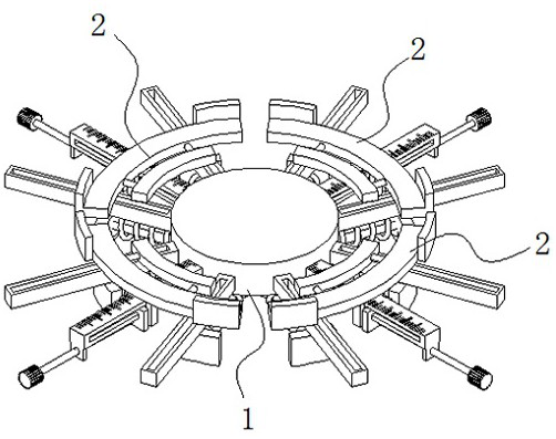
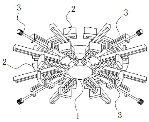
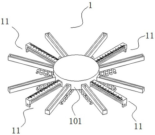
[0040] see Figure 1-9 , the present invention is a magnetostrictive workpiece support mechanism based on moving components, including an installation component 1, a support component 2 and a magnetic drive component 3; wherein, a plurality of support components 2 arranged in a circular direction are used to support the workpiece, and the The magnetic drive assembly 3 realizes the magnetic drive of the support assembly 2;

[0041] The installation assembly 1 inclu...


PUM


Abstract

The invention discloses a magnetostrictive workpiece support mechanism based on a moving assembly, and relates to the technical field of support mechanisms. The invention includes a mounting assembly, a supporting assembly and a magnetic drive assembly; the mounting assembly includes a fixed seat; several rod groups are fixedly connected to the sides of the fixed seat; Sliding fit between them; thread fit between magnetic drive component and rod set; magnetic repulsion between magnetic drive component and support component. The present invention is provided with a rod group, a fixed seat, a support assembly and a measuring ruler, and slides the support assembly along the rod group to flexibly adjust the spacing of a plurality of support assemblies arranged in the circumferential direction, thereby realizing the flexible adjustment of the support area, and further It meets the support of workpieces with different diameters, and at the same time, according to the approximate diameter of the workpiece to be supported, multiple support components can be directly adjusted to the appropriate position by using the measuring ruler, which greatly shortens the debugging time of workpiece support.

Description

technical field [0001] The invention belongs to the technical field of support mechanisms, in particular to a magnetostrictive workpiece support mechanism based on a moving assembly. Background technique [0002] When the workpiece is processed, it is necessary to support and fix the workpiece with the support platform. The support platform not only needs to support the workpiece, but also fix and position the workpiece to ensure the stability of the workpiece during processing. Chinese Patent Publication No. CN108818347A is a large-scale workpiece supporting mechanism, which includes a workbench, a central fixed cylinder and a first support mechanism. The center of the top of the workbench is fixed with a central fixed cylinder, and the center of the central fixed cylinder is provided with a fixed column. , the top of the central fixed cylinder is engaged with a central cover plate, and the bottom of the central cover plate is equidistantly embedded with four reinforcing cy...

Claims


Application Information

Patent Timeline
Patent Type & Authority Patents(China)
IPC IPC(8): B23Q3/154B25B11/00
CPCB23Q3/1543B25B11/002
Inventor 刘小娟
Owner 合肥德纳达信息科技有限公司
Learn More