Automatic grinding equipment
A kind of equipment and platform technology, applied in the field of automatic grinding equipment, can solve the problems of being easily scratched and heavy workload of injection molded structural parts, and achieve the effect of effective and rapid removal, improving efficiency and improving the precision of grinding
- Summary
- Abstract
- Description
- Claims
- Application Information
AI Technical Summary
Problems solved by technology
Method used
Image
Examples
Embodiment 1
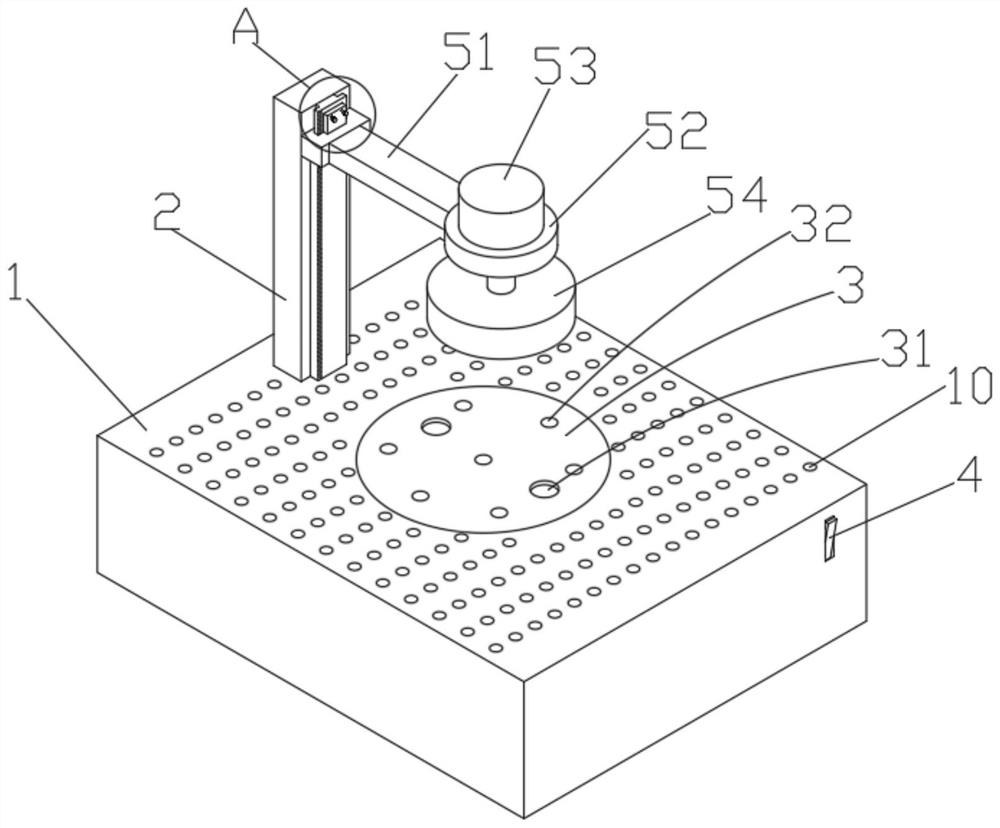
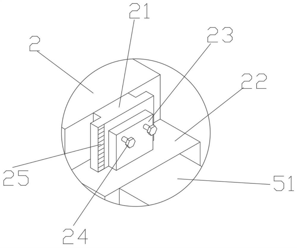
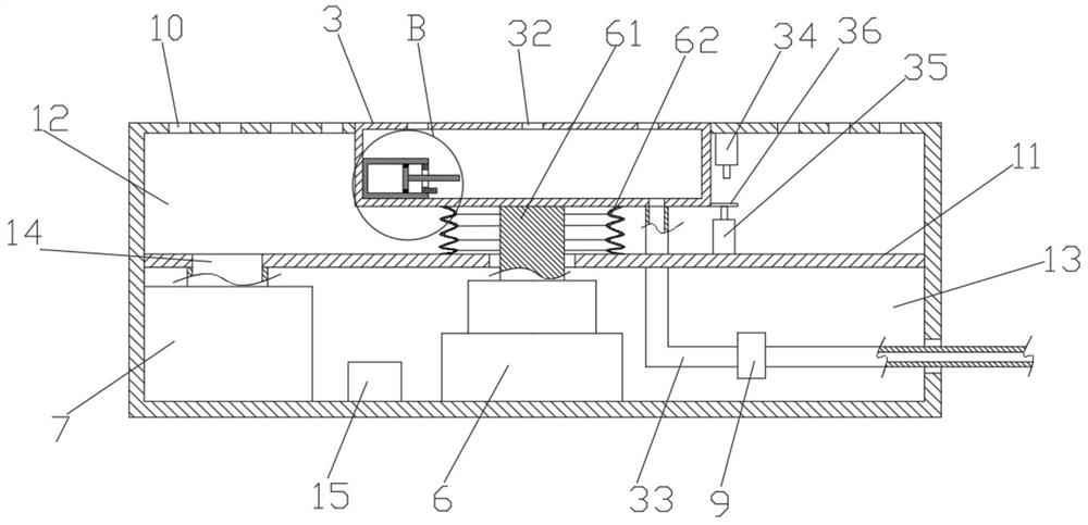
[0033] Such as Figure 1-3 The shown automatic grinding equipment includes a grinding platform 1, a lifting device is provided in the middle of the grinding platform 1, the grinding platform 1 is a hollow box, and a partition 11 is installed inside the grinding platform 1, and the partition 11 will grind the inside of the platform 1 Divided into an upper chamber 12 and a lower chamber 13, the lifting device includes a bearing part 3 and a lifting motor 6, the lifting motor 6 is installed on the bottom of the grinding platform 1 below the partition 11, and the push rod 61 of the lifting motor 6 passes through the partition 11, and the bearing part 3 is installed on the top of the push rod 61 of the lifting motor 6, the upper surface of the bearing part 3 is coplanar with the grinding platform 1, and the side surface of the bearing part 3 is provided with a contact piece 36, and the grinding platform above the contact piece 36 The first stroke switch 34 is installed on the lower...
Embodiment 2
[0037] As a further preferred technical solution, such as Figure 1-3 As shown, dust remover 7 is also installed in lower cavity 13, and dust remover 7 is communicated with upper cavity 12, and the upper surface of polishing platform 1 is provided with several suction holes 10, and dust remover 7 is connected with power switch 4 After connecting and turning on the power switch, the dust collector starts to work, so that the dust generated during the grinding process is sucked into the dust suction hole, and enters the dust collector through the upper chamber, avoiding the dust during the grinding process from polluting the environment.
[0038] An elastic rubber ring 62 is also installed between the bearing part 3 and the dividing plate 11, and the push rod 61 of the lifting motor 6 is located in the elastic rubber ring 62, so as to avoid polluting the lifting motor 6 by dust generated in the grinding process.
Embodiment 3
[0040] As a further preferred technical solution, such as Figure 1-4 As shown, the carrying portion 3 is a hollow cylindrical structure, and the upper surface of the carrying portion 3 is provided with several through holes 32 and limiting grooves 31, and the inside of the carrying portion 3 is provided with a pressure switch, the pressure switch and the control circuit. The board 15 is electrically connected, and when the pressure switch is closed, the control circuit board 15 controls the push rod 61 of the lifting motor 6 to rise, and the bottom of the bearing part 3 is also provided with a suction hole, and a high-pressure pipe 33 passing through the partition 11 is installed on the suction hole. A solenoid valve 9 is installed on the high-pressure pipe 33, the solenoid valve 9 is electrically connected to the control circuit board 15, and the high-pressure pipe 33 is connected to an external vacuum pipeline.
[0041] The pressure switch includes a cylinder 81 with an ope...
PUM
 Abstract
Description
Claims
Application Information
 - R&D
- Intellectual Property
- Life Sciences
- Materials
- Tech Scout
- Unparalleled Data Quality
- Higher Quality Content
- 60% Fewer Hallucinations
Browse by: Latest US Patents, China's latest patents, Technical Efficacy Thesaurus, Application Domain, Technology Topic, Popular Technical Reports.
© 2025 PatSnap. All rights reserved.Legal|Privacy policy|Modern Slavery Act Transparency Statement|Sitemap|About US| Contact US: help@patsnap.com


