
Anti-adhesion kitchen knife

An anti-adhesion and kitchen knife technology, applied in the field of kitchen utensils, can solve problems such as hand injury, and achieve the effects of avoiding hand sliding, improving comfort, and increasing friction.

Pending Publication Date: 2021-06-11
吴德超
View PDF0 Cites 1 Cited by
  • Summary
  • Abstract
  • Description
  • Claims
  • Application Information

AI Technical Summary

Problems solved by technology

[0005] The technical problem to be solved by the present invention is to provide an anti-adhesion kitchen knife, one of which is to increase the friction between the hand and the hand, and solve the problem that the hand is easily injured due to the sliding between the palm and the knife handle

Method used


Image

  • Anti-adhesion kitchen knife
  • Anti-adhesion kitchen knife
  • Anti-adhesion kitchen knife

Examples


Embodiment 1

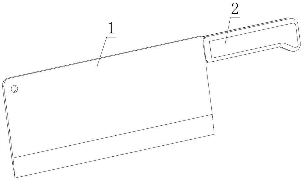
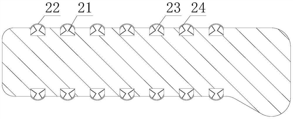
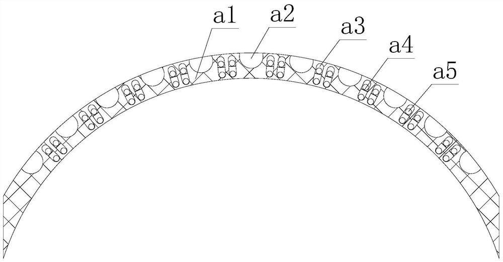
[0024] Such as figure 1 - image 3 As shown, the present invention provides an anti-adhesion kitchen knife, comprising a knife body 1, one end of the knife body 1 is fixedly connected with a knife handle 2, the upper and lower ends of the outer side of the knife handle 2 are provided with an air cavity 21, and the air cavity 21 is far away from the knife handle 2 An anti-slip film 22 is fixedly connected to one end of the air cavity 21, and a support elastic piece 23 is arranged between the side wall of the air cavity 21 and the anti-slip film 22. A bumper ball 24 is fixedly connected.

[0025] Wherein, the anti-slip film 22 is provided with a rubber layer a1 inside, and the side of the rubber layer a1 away from the air cavity 21 is provided with an extrusion chamber a2, and the inner part of the rubber layer a1 is provided with a vibration chamber a3, and the middle part of the vibration chamber a3 is fixed. The vibrating partition a4 is connected, and the vibrating chamber...

Embodiment 2

[0028] Such as Figure 4-6 As shown, on the basis of Embodiment 1, the present invention provides a technical solution: the inside of the extrusion chamber a2 is provided with a chamber shell s1, the upper ends of both sides of the chamber shell s1 are movably connected with rollers s2, the chamber shell s1 A vibrating rod s3 is arranged inside, and both ends of the vibrating rod s3 are fixedly connected with the rubber layer a1.

[0029] Wherein, the inside of the vibrating rod s3 is provided with a connection end d1, the number of the connection ends d1 is two, a connection rod d2 is fixedly connected between the two connection ends d1, and the number of connection rods d2 set between the two connection ends d1 is Five, five connecting rods d2 are fixedly connected with percussion partitions d3, and vibration balls d4 are arranged between the five connecting rods d2.

[0030] The vibrating ball d4 is provided with a spherical shell e1 inside, the spherical shell e1 is provi...


PUM


Abstract

The invention discloses an anti-adhesion kitchen knife, and relates to the technical field of kitchen utensils. The kitchen knife comprises a knife body, one end of the knife body is fixedly connected with a knife handle, air cavities are formed in the upper end and the lower end of the outer side of the knife handle, and the ends, away from the knife handle, of the air cavities are fixedly connected with anti-skid films. Through combination of the anti-skid films and supporting elastic pieces, when the knife handle is held, the anti-skid films are deformed through the extrusion force of a palm, extrusion cavities shrink, an oil layer on the palm is scraped off, and thus the friction force between the knife handle and the palm is improved; when the knife handle is loosened, the extrusion force disappears, the anti-skid films are rapidly reset through the pressure of compressed gas, impact ball knock the anti-skid films through the elasticity of the supporting elastic pieces, the anti-skid films vibrate, and meanwhile, shaking balls impact in a shaking cavity, so that a rubber layer and a shaking partition plate are impacted, vibration of the rubber layer is intensified, oil in a connecting rod is removed in a shaking mode, thus the knife handle can be conveniently held next time, and the friction force between the palm and the knife handle during holding can be increased.

Description

technical field [0001] The invention relates to a kitchen knife, relates to the technical field of kitchen utensils, in particular to an anti-adhesion kitchen knife. Background technique [0002] A kitchen knife is a kind of kitchen utensil. Its main purpose is to cut food or carve food, etc. It can be divided into stainless steel knife and iron knife, and can also be divided into Chinese style kitchen knife, Japanese style kitchen knife and foreign style kitchen knife. There are following problems at prior art: [0003] 1. In the prior art, when cutting some oily food materials, there is oil attached to the hand, so it is easy to slip when holding the knife, which makes the holding knife unstable and easy to cut fingers; [0004] 2. In the prior art, for some chefs, it will affect the cooking of the ingredients, and then the original intention of being convenient for cutting vegetables cannot be achieved, and the applicability of the kitchen knife becomes worse. Therefore,...

Claims


Application Information

Patent Timeline
Patent Type & Authority Applications(China)
IPC IPC(8): B26B3/00B25G1/00
CPCB25G1/00B26B3/00
Inventor 吴德超
Owner 吴德超
Learn More