Device for precisely positioning and recycling three-legged walking stick stool through hot melting
A technology of precise positioning and recycling devices, applied in the field of renewable resources, can solve problems such as easy wear and tear of plastic parts, injuries, and limited service life
- Summary
- Abstract
- Description
- Claims
- Application Information
AI Technical Summary
Problems solved by technology
Method used
Image

Examples
Embodiment 1
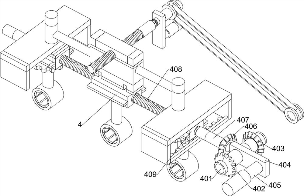
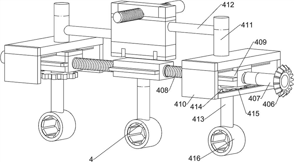
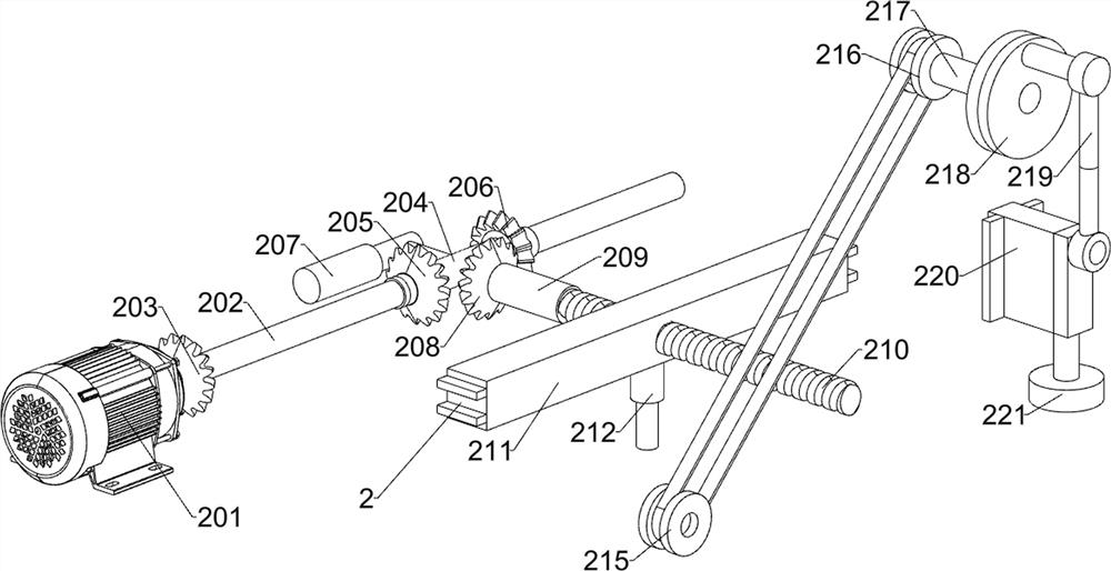
[0032] A three-legged crutch stool through hot-melt precise positioning recovery device, such as Figure 1-11 As shown, it includes a floor assembly 1, an armrest separation unit 2, a seat cushion separation unit 3, a foot separation unit 4 and a control panel 5; the floor assembly 1 is connected to the armrest separation unit 2; the floor assembly 1 is connected to the seat cushion separation unit 3 ; The floor assembly 1 is connected to the foot separation unit 4 ; the bottom plate assembly 1 is connected to the control panel 5 ; the armrest separation unit 2 is connected to the foot separation unit 4 .
[0033] When in use, first place a three-legged crutch stool to the desired position through the hot-melt precise positioning recovery device, then connect the external power supply, and start it through the control panel 5; The armrest separation unit 2 fixed on the base plate assembly 1, because the three-legged crutch stool is used for a long time, it is easy to cause the...
PUM
 Abstract
Description
Claims
Application Information
 - R&D
- Intellectual Property
- Life Sciences
- Materials
- Tech Scout
- Unparalleled Data Quality
- Higher Quality Content
- 60% Fewer Hallucinations
Browse by: Latest US Patents, China's latest patents, Technical Efficacy Thesaurus, Application Domain, Technology Topic, Popular Technical Reports.
© 2025 PatSnap. All rights reserved.Legal|Privacy policy|Modern Slavery Act Transparency Statement|Sitemap|About US| Contact US: help@patsnap.com