
Precision Machining Forming Die for High Precision Miniature Power Transmission Ring Process Bushing

A technology of precision machining and forming molds, which is applied to household appliances, other household appliances, and other applications. It can solve the problems of small screw size, large warping deformation, and low strength, so as to improve assembly accuracy and strength, and reduce warpage. The degree of warping, avoiding the effect of randomness

Active Publication Date: 2022-05-20
惠州市硕贝德精工技术有限公司
View PDF6 Cites 0 Cited by
  • Summary
  • Abstract
  • Description
  • Claims
  • Application Information

AI Technical Summary

Problems solved by technology

In actual production, the technology of the 1950s has been used, and the molding structure of the relevant traditional molds is as follows: Figure 9 and 10 As shown, the parts formed by the original mold have always had large warpage and deformation, and some key dimensions cannot meet the product design requirements. It is necessary to change the product design drawings, or use it out of tolerance, and it is difficult to improve the pass rate of subsequent assembly and processing.
[0003] The traditional mold design is based on the introduction and design of various textbooks and professional reference materials. The main fixing method of the forming core is cylindrical pin positioning and screw fixing. The screw size is small, the strength is low, and the fixing is easy to fail. The position of the mouth is very random, causing the key dimensions of some parts to be out of tolerance, and the dimensions are unstable

Method used


Image

  • Precision Machining Forming Die for High Precision Miniature Power Transmission Ring Process Bushing
  • Precision Machining Forming Die for High Precision Miniature Power Transmission Ring Process Bushing
  • Precision Machining Forming Die for High Precision Miniature Power Transmission Ring Process Bushing

Examples


Embodiment Construction

[0024] The following will be combined with the accompanying drawings in the embodiments of the present invention, the technical solution in the embodiments of the present invention will be described clearly and completely, it is clear that the embodiments described are only a part of the embodiment of the present invention, not all embodiments. Based on embodiments in the present invention, all other embodiments obtained by those of ordinary skill in the art without making creative work, are within the scope of protection of the present invention.

[0025] It should be noted that, in this context, the term "comprising", "comprising" or any other variation thereof is intended to cover non-exclusive inclusion, so that a process, method, article or apparatus comprising a series of elements includes not only those elements, but also other elements not expressly listed, or also includes elements inherent in such processes, methods, articles or equipment. Without more restrictions. The el...


PUM


Abstract

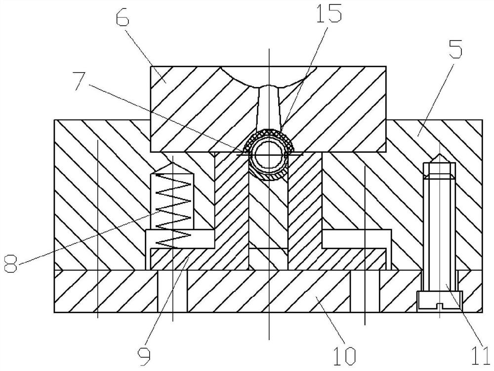
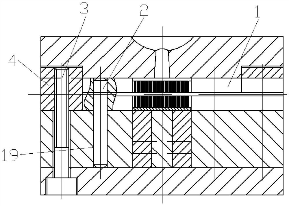
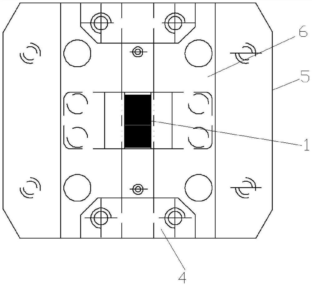
Provide a precision machining molding mold for high-precision miniature power transmission ring process bushings, innovatively design the fixing method of the core molding part of the mold, make the combined core fixing method adopt cylindrical positioning pins for positioning, screw I to fix and position the pressing block, and position The compression block compresses and fixes the combined core; and the front and rear sides of the die are positioned by the step structure on both sides of the upper surface of the fixed plate, and the left and right sides of the die are positioned by the positioning compression blocks, so that the die can be positioned effectively in all directions. Therefore, the positioning of the core molding part of the mold and the fixed part are reliable, the assembly accuracy and strength of the mold are improved, the service life of the mold is improved, and the parameters of injection molding, cooling temperature gradient, and injection molding plastic flow direction of the injection molding system are convenient to be adjusted, and the randomness of the gate position is avoided. Some key dimensions of the parts are out of tolerance, and the dimensions are unstable, reducing the degree of warping of plastic parts during injection molding, and improving the qualified rate of bushings in injection molding assembly processes.

Description

Technical field [0001] The present invention belongs to the field of mold technology, specifically relates to a precision machined molding mold for high-precision micro transmission ring process bushings. Background [0002] Micro precision power transmission accessories are the core transmission components of a certain type of equipment, and their assembly, processing and molding are realized by assembling process bushings, and the process bushing structure is basically similar Figure 5 and 6 As shown, it is only how different the positioning ring is, the more positioning grooves, the greater the warpage deformation, such as Figure 7 and 8 as shown. In actual production, the technology of the 1950s has always been used, and the molding structure of the traditional mold is related to it Figure 9 and 10 As shown, the original mold molded parts have always had large warped deformation, some key dimensions can not meet the product design requirements, the need for product design to ...

Claims


Application Information

Patent Timeline
Patent Type & Authority Patents(China)
IPC IPC(8): B29C45/36B29C45/26B29L31/34
CPCB29C45/36B29C45/26B29L2031/34
Inventor 郭兰生任平舒燕
Owner 惠州市硕贝德精工技术有限公司
Learn More