Anaerobic tower for sewage treatment

A sewage treatment and anaerobic tower technology, applied in the direction of anaerobic digestion treatment, etc., can solve the problems of increasing the dead angle of water flow, reducing the proliferation speed of anaerobic microorganisms, etc., and achieve the effect of improving reset assist, reducing dead angle of water flow, and improving the degree of water turbulence

Inactive Publication Date: 2021-06-11
广东国隆再生资源有限公司
View PDF0 Cites 0 Cited by
  • Summary
  • Abstract
  • Description
  • Claims
  • Application Information

AI Technical Summary

Problems solved by technology

[0002] The anaerobic tower is a common sewage treatment equipment. Usually, the bottom of the anaerobic tower is equipped with a water distributor, the top of the anaerobic tower is equipped with a three-phase separator, and the anaerobic tower is equipped with a sludge bed. The sewage is distributed from the bottom of the anaerobic tower. The water tank enters the anaerobic tower, and there are a large number of anaerobic microorganisms in the sludge bed. After the sewage enters the sludge bed, the organic matter in the sewage is decomposed into biogas by anaerobic microorganisms. The sludge bed of the existing sewage treatment anaerobic tower Aeration will be used to provide oxygen to the activated sludge above it, so that a large amount of foam will be generated in the placement tank, because the foam will have the effect of floating up, so that the bubbles that float up will bulge and stick to the bottom of the sludge bed. Cause the through hole of the sludge bed to be blocked and adsorb the activated sludge nearby, increase the dead angle of water flow, and reduce the growth rate of anaerobic microorganisms

Method used


Image

  • Anaerobic tower for sewage treatment
  • Anaerobic tower for sewage treatment
  • Anaerobic tower for sewage treatment

Examples


Embodiment 1

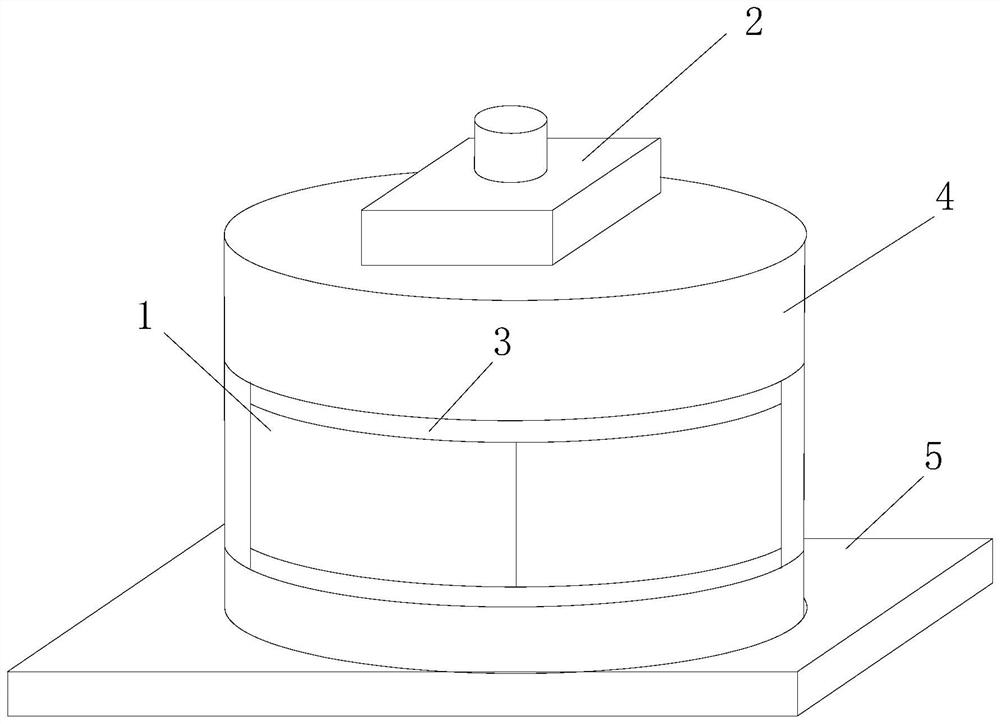
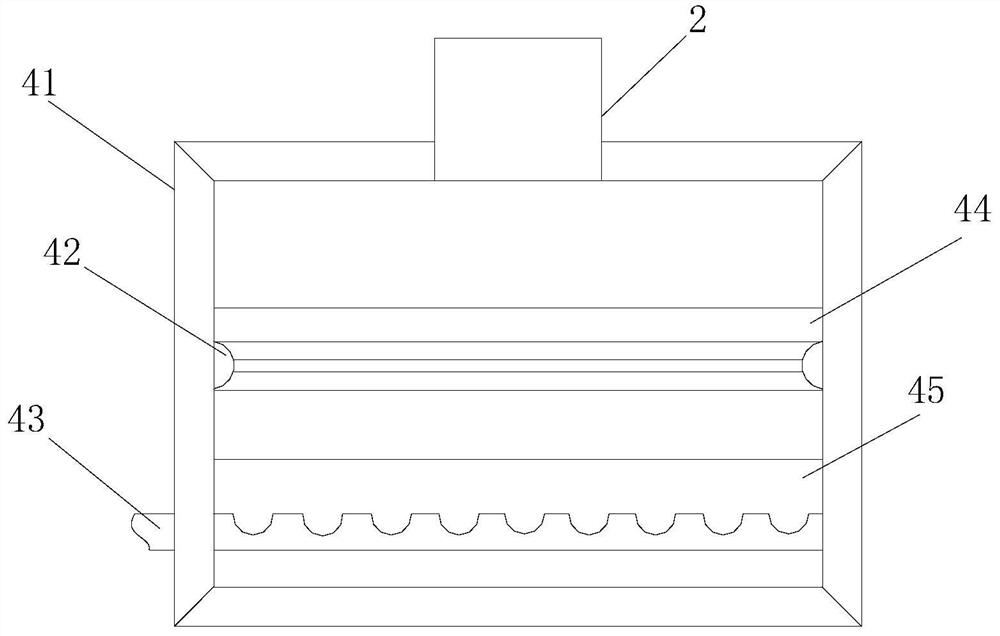
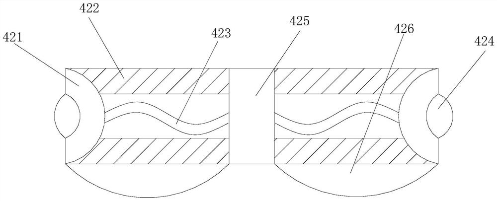
[0027] Such as Figure 1-Figure 3 As shown, the present invention provides an anaerobic tower for sewage treatment, its structure includes a gate 1, a water distributor 2, a sealing sleeve 3, a tower shell 4, and a base 5, and the gate 1 is installed on the tower shell 4 through a sealing sleeve 3 On the outer surface, the tower shell 4 is provided with a water distributor 2 and a base 5 respectively, and the tower shell 4 includes a tower body 41, a booster device 42, an aeration pipe 43, a sludge bed 44, and a placement pool 45. The top of the tower body 41 is fixedly connected to the bottom of the water distributor 2, and a sludge bed 44 is fixedly connected inside it. The bottom of the sludge bed 44 is provided with a booster device 42, and the booster device 42 is transitionally matched with the placement pool 45. An aeration pipe 43 is socketed inside the placement pool 45, and the booster device 42 includes a roller table 421, a running-in belt 422, a telescopic rope 42...

Embodiment 2

[0029] Such as Figure 4-Figure 7 As shown, on the basis of Embodiment 1, the present invention combines the mutual cooperation of the following structural components. Fixedly connected with a telescopic rope 423, the other side is welded and connected with a receiving seat 253, and a connecting column 254 is embedded and connected to the receiving seat 253, and the top of the connecting column 254 is hingedly connected with a docking shaft 252, and the docking shaft 252 It is a structure that is buckled by two rings. When it is tight, it will be buckled and straightened instantly, and it will be vertically crossed between the connecting columns 254 to provide a power source for the next rotation. The defoaming structure 426 includes adsorption mouth 261, outer limit seat 262, condensation sleeve 263, cutting plate 264, rolling rod 265, measuring point chamber 266, the suction port 261 is socketed and connected inside the groove position of the outer limit seat 262 through the...


PUM


Abstract

The invention discloses an anaerobic tower for sewage treatment, which structurally comprises a gate, a water distributor, a sealing sleeve, a tower shell and a base, the gate is installed on the tower shell through the sealing sleeve, the tower shell is provided with the water distributor and the base, a power assisting device is provided with a fixed accessory and a defoaming structure, and a running-in belt is matched with the fixed accessory and the defoaming structure, when floating bubbles are attached to the bottom of a sludge bed, buoyancy brought by the bubbles enables the sludge bed to be separated from limitation of the running-in belt, the running-in belt twists in a snakelike mode between the fixing shafts with the fixing accessory as a fulcrum, it is guaranteed that the bubble removing structure can remove bubbles sufficiently, the water disorder degree can be improved, and water flow dead angles are reduced.

Description

technical field [0001] The invention relates to the field of sewage treatment, in particular to an anaerobic tower for sewage treatment. Background technique [0002] The anaerobic tower is a common sewage treatment equipment. Usually, the bottom of the anaerobic tower is equipped with a water distributor, the top of the anaerobic tower is equipped with a three-phase separator, and the anaerobic tower is equipped with a sludge bed. The sewage is distributed from the bottom of the anaerobic tower. The water tank enters the anaerobic tower, and there are a large number of anaerobic microorganisms in the sludge bed. After the sewage enters the sludge bed, the organic matter in the sewage is decomposed into biogas by anaerobic microorganisms. The sludge bed of the existing sewage treatment anaerobic tower Aeration will be used to provide oxygen to the activated sludge above it, so that a large amount of foam will be generated in the placement tank, because the foam will have the...

Claims


Application Information

Patent Timeline
Patent Type & Authority Applications(China)
IPC IPC(8): C02F3/28
CPCC02F3/28
Inventor 陈燕玉
Owner 广东国隆再生资源有限公司
Why Eureka
Try Eureka