
Clamping device and hydraulic system of pile driver

A hydraulic system, clamping device technology, applied in the direction of fluid pressure actuators, sheet pile walls, mechanical equipment, etc., can solve problems such as life-threatening, safety, damage to surrounding buildings and construction machinery, to avoid damage and improve safety effect

Pending Publication Date: 2021-06-11
SHANDONG LINGONG CONSTR MACHINERY
View PDF0 Cites 0 Cited by
  • Summary
  • Abstract
  • Description
  • Claims
  • Application Information

AI Technical Summary

Problems solved by technology

The vibration frequency of the vibrating hammer head is usually between 20 and 40 Hz. During the piling or pile pulling process, when the hydraulic system control fails, the vibrating hammer head may be unclamped, which will cause the pile to fall to the ground easily. The nearby pile support personnel, the driver in the cab and the residents around the construction cause life threats; cause damage to surrounding buildings and construction machinery, etc.
At the same time, when the whole machine is operated to stop the vibration of the vibrating hammer head, under the action of inertial force, the vibrating hammer head will continue to vibrate, and the internal friction resistance of the excitation mechanism and the stirring resistance of the gear oil will stop the vibration. Long, it is easy to cause damage to the card slot of the pile and also poses a safety hazard

Method used


Image

  • Clamping device and hydraulic system of pile driver
  • Clamping device and hydraulic system of pile driver

Examples


Embodiment Construction

[0040]In order to make the technical problems solved by the present invention, the technical solutions adopted and the technical effects achieved clearer, the technical solutions of the embodiments of the present invention will be further described in detail below in conjunction with the accompanying drawings. Obviously, the described embodiments are only the technical solutions of the present invention. Some, but not all, embodiments. Based on the embodiments of the present invention, all other embodiments obtained by those skilled in the art without making creative efforts belong to the protection scope of the present invention.

[0041] In the description of the present invention, unless otherwise clearly specified and limited, the terms "connected", "connected" and "fixed" should be understood in a broad sense, for example, it can be a fixed connection, a detachable connection, or an integrated ; It can be a mechanical connection or an electrical connection; it can be a di...


PUM


Abstract

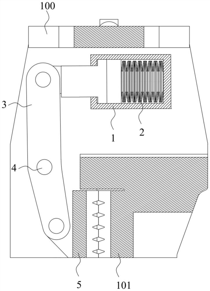
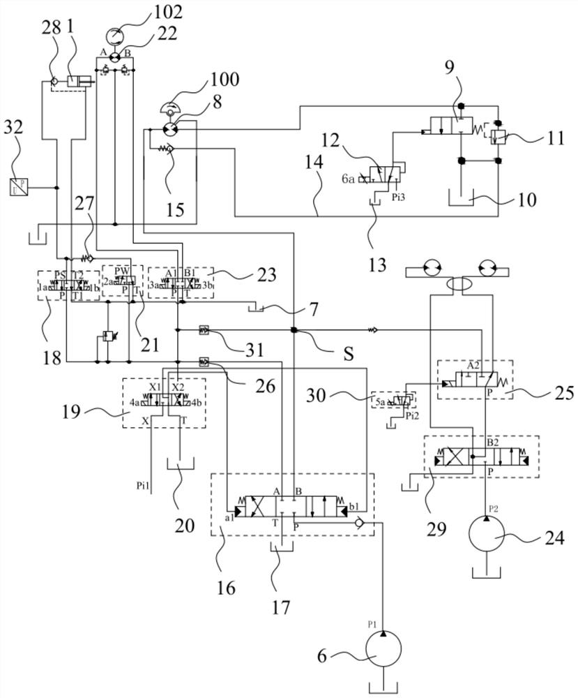
The invention discloses a clamping device and a hydraulic system of a pile driver, and relates to the technical field of engineering machinery. The clamping device of the pile driver is arranged on a hammer body of a vibration hammer head and used for clamping a pile, the clamping device comprises a clamping oil cylinder, a connecting rod and a clamping piece, wherein the clamping oil cylinder is fixed to the hammer body, a piston and a piston rod connected with the piston are arranged in the clamping oil cylinder, an elastic piece is arranged in a rodless cavity of the clamping oil cylinder, the two ends of the elastic piece in the telescopic direction abut against the inner wall of the clamping oil cylinder and the piston, the extension direction of the connecting rod and the extension direction of the piston rod form an angle, one end of the connecting rod is slidably connected with the piston rod, the connecting rod is rotationally connected with the hammer body through a rotating part, the rotating part and the two ends of the connecting rod are arranged at an interval, the clamping piece is slidably connected with the other end of the connecting rod, an abutting portion is arranged on the hammer body, and the elastic piece can enable the piston rod to stretch out of the clamping oil cylinder to drive the clamping piece to move so that the pile can abut against the abutting portion. According to the clamping device, clamping can be achieved through the structure of the clamping device, so that clamping disengaging can be avoided, and safety is improved.

Description

technical field [0001] The invention relates to the technical field of engineering machinery, in particular to a clamping device and a hydraulic system of a pile driver. Background technique [0002] Crawler-type hydraulic pile drivers have been rapidly applied in high-speed railways, highway soft ground treatment, reclamation and bridges, wharf engineering, deep foundation pit support and foundation treatment of ordinary buildings, etc., and can be used for piling steel pipes, steel plates, and wood And building materials, etc., greatly improving the efficiency of piling operations, saving a lot of time and cost. [0003] The crawler hydraulic pile driver can be divided into three parts: the fuselage, the arm and the vibrating hammer head. The fuselage is basically the same as that of the excavator, and the arm is customized according to the model of the fuselage and the required piling depth. The functions of the vibrating hammer head mainly include clamping and vibration...

Claims


Application Information

Patent Timeline
IPC IPC(8): E02D7/14F15B15/22F15B13/02F15B13/01
CPCE02D7/14F15B13/01F15B13/02F15B13/027F15B15/226
Inventor 苗国华杨典作刘震李强
Owner SHANDONG LINGONG CONSTR MACHINERY
Learn More