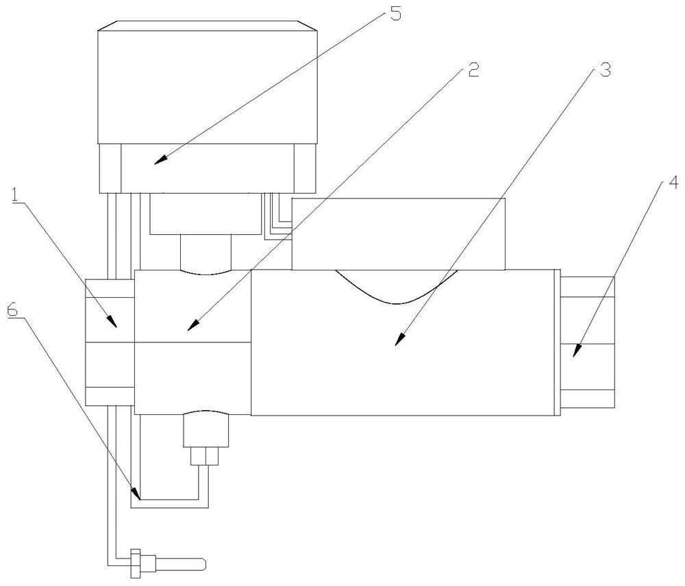
Heat supply control valve with accurate metering function

A control valve, precise technology, applied to valve details, valve devices, cocks including cut-off devices, etc., can solve the problems of uncompact structure, many auxiliary parts, easy to damage, etc., to overcome the complexity of auxiliary parts, prolong the service life, The effect of reducing maintenance costs

Pending Publication Date: 2021-06-11
山东齐芯智控科技有限公司
View PDF8 Cites 2 Cited by
  • Summary
  • Abstract
  • Description
  • Claims
  • Application Information

AI Technical Summary

Problems solved by technology

[0002] The electric ball valve used in traditional heating is an executive control valve, which cannot realize closed-loop feedback control, so it cannot realize independent control of flow or power constant. If the traditional electric ball valve is used to achieve constant control of flow or power, it is necessary to An automatic controller is added on the basis of the sensor, which can be realized through a closed-loop algorithm. The traditional scheme has many auxiliary accessories, is easy to be damaged, and the structure is not compact. Therefore, the precise closed-loop control of the flow rate or heating power of a single household has not yet been realized in the heating industry.
[0003] For example, the Chinese patent CN 201382825 Y "New Heat Regulating Controller" discloses a heat regulating controller composed of a heat metering component and an electric regulating valve. An integrator is used to regulate the valve according to the temperature measured by the temperature sensor. Its working principle is the same as The above description is consistent, and the closed-loop algorithm is used to control the valve, and there are many auxiliary accessories and the structure is not compact, which is not conducive to large-scale promotion and use, and the later maintenance cost is high

Method used


Image

  • Heat supply control valve with accurate metering function

Examples


Embodiment Construction

[0021] The present invention will be further described below in conjunction with the accompanying drawings and embodiments.

[0022] The structures, proportions, sizes, etc. shown in the drawings attached to this specification are only used to match the content disclosed in the specification for the understanding and reading of those who are familiar with this technology, and are not used to limit the conditions for the implementation of the present invention , so it has no technical substantive meaning, and any modification of structure, change of proportional relationship or adjustment of size shall still fall within the scope of the disclosure of the present invention without affecting the functions and objectives of the present invention. within the scope of the technical content covered. At the same time, terms such as "upper", "lower", "left", "right", "middle" and "one" quoted in this specification are only for the convenience of description and are not used to limit th...


PUM


Abstract

The invention discloses a heat supply control valve with an accurate metering function. The heat supply control valve with the accurate metering function comprises pipeline connectors, an electromagnetic flowmeter, an electric ball valve, a water inlet temperature sensor, a water return temperature sensor and a control device, wherein when the device is transversely placed as a whole, the first pipeline connector, the electric ball valve, the electromagnetic flowmeter and the second pipeline connector are sequentially connected from left to right; and the control device is fixedly connected to the upper side of the electric ball valve, and a through hole for the water inlet sensor to insert is formed in the lower side of the electric ball valve. According to the invention, the electric ball valve, the electromagnetic flowmeter, the water inlet temperature sensor, the water return temperature sensor and a measurement control circuit are integrated to form a closed-loop feedback control system, constant-flow heat supply or constant-power heat supply of the heat supply system can be realized, and the heat supply control valve with the accurate metering function is the optimal product for achieving balance of a heat supply pipe network and reasonable heat distribution, and has very positive significance on energy conservation and consumption reduction of the heat supply system.

Description

technical field [0001] The invention relates to the technical field of control valves, in particular to a precisely metered heating control valve. Background technique [0002] The electric ball valve used in traditional heating is an executive control valve, which cannot realize closed-loop feedback control, so it cannot realize independent control of flow or power constant. If the traditional electric ball valve is used to achieve constant control of flow or power, it is necessary to An automatic controller is added on the basis of the sensor, which can be realized through a closed-loop algorithm. The traditional scheme has many auxiliary accessories, is easy to be damaged, and the structure is not compact. Therefore, the precise closed-loop control of the flow rate or heating power of a single household has not yet been realized in the heating industry. . [0003] For example, the Chinese patent CN 201382825 Y "New Heat Regulating Controller" discloses a heat regulating ...

Claims


Application Information

Patent Timeline
Patent Type & Authority Applications(China)
IPC IPC(8): F16K37/00F16K31/06F16K5/06
CPCF16K37/0041F16K31/06F16K5/06
Inventor 王强郭荣岭
Owner 山东齐芯智控科技有限公司
Why Eureka
Try Eureka