Steam generating device

A technology of steam generating device and liquid level position, which is applied in the direction of steam generation, steam generation method, control system, etc., and can solve the problems of safety and hidden dangers of isopropanol vapor, difficulty in controlling the concentration and stability of isopropanol vapor, etc. Achieve the effect of stabilizing the process and avoiding potential safety hazards

Pending Publication Date: 2021-06-11
ACM RES SHANGHAI
View PDF0 Cites 2 Cited by
  • Summary
  • Abstract
  • Description
  • Claims
  • Application Information

AI Technical Summary

Problems solved by technology

[0006] In view of the above-mentioned shortcomings of the prior art, the object of the present invention is to provide a steam generating device for solving the potential safety hazards in the prior art obtained by heating the isopropanol vapor, and the concentration and stability of the isopropanol vapor Unmanageable problems

Method used


Image

  • Steam generating device

Examples


Embodiment 1

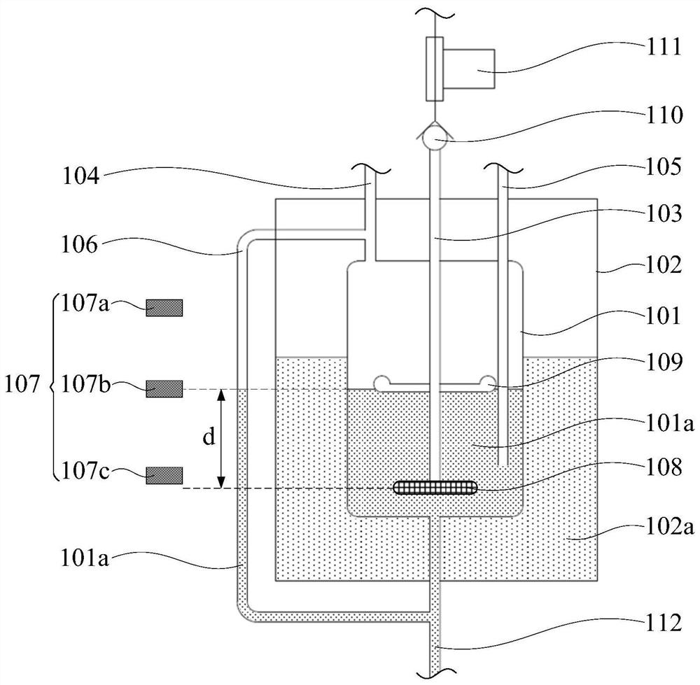
[0045] see figure 1 , the present embodiment provides a steam generating device, comprising:

[0046] A liquid medicine storage tank 101, which is used to accommodate the liquid medicine 101a;

[0047] Medium heat preservation tank 102, which is used to accommodate heat preservation medium 102a with a set temperature; said liquid medicine storage tank 101 is placed in said medium heat preservation tank 102, and said liquid medicine storage tank 101 makes The medicinal liquid 101a maintains a set temperature;

[0048] A carrier gas supply module, which includes a carrier gas source for providing carrier gas and a carrier gas supply pipeline 103; the carrier gas supply pipeline 103 includes an inlet end and an outlet end, and the inlet end is connected to the carrier gas source, The gas outlet end extends into the liquid medicine 101a; the carrier gas supply module also includes a carrier gas distribution unit installed at the gas outlet end of the carrier gas supply pipeline ...

Embodiment 2

[0063] This embodiment provides a steam generating device. Compared with Embodiment 1, the difference of this embodiment is that the steam generating device includes a plurality of carrier gas distribution units, that is, a plurality of nano gas disc stones. The plurality of nano-gas disk stones can all keep the same definite distance from the liquid liquid surface, be evenly distributed in the horizontal plane at the same height in the liquid liquid storage tank, and be connected to the same carrier gas supply pipeline. Optionally, there are six nano gas disc stones, and the connecting lines of adjacent individuals form a regular hexagon, so as to be evenly distributed in the horizontal plane where they are located. The quantity of the nano gas rocks can be adjusted according to the size and shape of the nano gas rocks. By arranging a plurality of uniformly distributed nano gas disc stones, the steam generating device provided in this embodiment improves the carrier gas suppl...


PUM


Abstract

The invention provides a steam generating device. The steam generating device comprises a liquid medicine storage tank; a medium heat preservation tank, wherein the medium heat preservation tank is used for containing a heat preservation medium with a set temperature, the liquid medicine storage tank is arranged in the medium heat preservation tank, and the liquid medicine storage tank makes contact with the heat preservation medium so that the liquid medicine can be kept at the set temperature; a carrier gas supply module, wherein the carrier gas supply module comprises a carrier gas source and a carrier gas supply pipeline, the carrier gas supply pipeline comprises a gas inlet end and a gas outlet end, the gas inlet end is connected with the carrier gas source, and the gas outlet end extends into the liquid medicine, and the carrier gas supply module further comprises a carrier gas distribution unit which is used for distributing carrier gas into bubbles and keeping a set distance from the liquid level of the liquid medicine; and a steam output pipeline, wherein the steam output pipeline is connected to the upper portion of the liquid medicine storage tank and is used for outputting carrier gas carrying liquid medicine steam. Constant temperature control is carried out through the water bath, potential safety hazards caused by direct heating are avoided, stable carrier gas supply is combined, the supplied isopropanol steam is high in content and stable in component, and it is ensured that stable process effect of the isopropanol is achieved.

Description

technical field [0001] The invention relates to the field of semiconductor manufacturing equipment, in particular to a steam generating device. Background technique [0002] In semiconductor manufacturing processes, wafers need to be dried after cleaning to remove moisture adhering to their surfaces. The following drying methods are usually used: spin drying, hot nitrogen drying, and isopropanol (IPA) slow pulling drying. Isopropanol slow pulling drying is more and more widely used in semiconductor wet processing because of the advantages of no residue and no damage. [0003] Isopropanol slow pulling drying is to use the low surface tension and volatile characteristics of isopropanol to achieve the purpose of drying the wafer water film. To dry the wafer, first immerse the wafer in deionized water filled with isopropanol vapor above the water surface. The wafer is slowly transferred from the water to the isopropanol atmosphere by slowly pulling the wafer or slowly drainin...

Claims


Application Information

Patent Timeline
Patent Type & Authority Applications(China)
IPC IPC(8): F22B1/28F22B35/00
CPCF22B1/28F22B35/00
Inventor 张少帅王俊吴均王晖
Owner ACM RES SHANGHAI
Why Eureka
Try Eureka