Passive optical device structural member capable of reducing light reflection

A passive light and light reflection technology, which is applied in the field of optical fiber communication, can solve the problems of easy heating and low power of optical isolators, achieve stable heat dissipation efficiency, increase ventilation area, and achieve dust-proof effects

Active Publication Date: 2021-06-11
NORTH CHINA UNIV OF WATER RESOURCES & ELECTRIC POWER
View PDF7 Cites 2 Cited by
  • Summary
  • Abstract
  • Description
  • Claims
  • Application Information

AI Technical Summary

Problems solved by technology

[0003]In the prior art, the power of commonly used optical isolators is generally low. There are some differences. Compared with low-power devices, high-power devices work at higher power and are more likely to generate heat. Therefore, the performance of devices is seriously affected by the thermal characteristics of materials and heat dissipation design. Effective measures must be taken to reduce the impact on The absorption of laser light and effective heat dissipation, for this reason we propose structural components of passive optical devices that reduce light reflection to solve the above problems

Method used


Image

  • Passive optical device structural member capable of reducing light reflection
  • Passive optical device structural member capable of reducing light reflection
  • Passive optical device structural member capable of reducing light reflection

Examples


Embodiment Construction

[0024] Next, the technical solutions in the embodiments of the present invention will be apparent from the embodiment of the present invention, and it is clearly described, and it is understood that the described embodiments are merely embodiments of the present invention, not all of the embodiments.

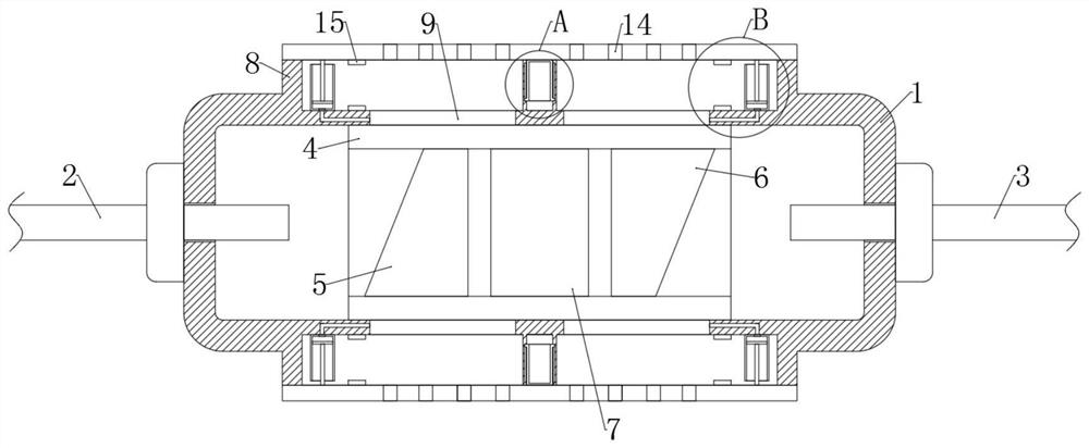
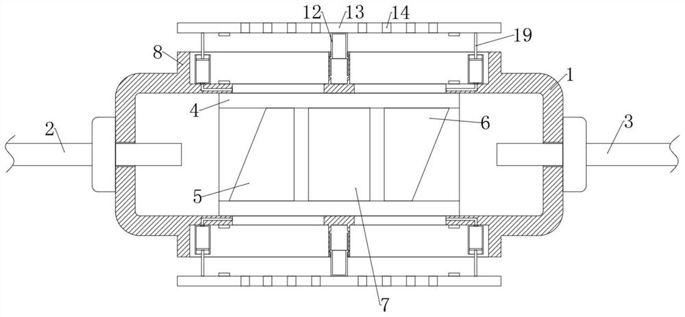
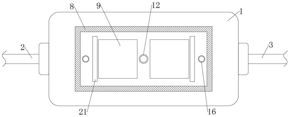
[0025] Refer Figure 1-6 , Reduce the structural member of the passive optical device of the light reflected, including the housing 1, the magnetic ring 4, the first wedge corner piece 5, the second wedge flap 6, the rotary sheet 7, and the magnetic ring 4 is fixedly attached to the housing 1. On the inner side wall, the first wedge flap 5, the second wedge cap 6, the rotary sheet 7 is fixed to the inside of the magnetic ring 4, respectively, the magnetic ring 4 is closely fitted to the inner side wall of the housing 1, avoiding dust into the device inside the device The end side wall of the housing 1 penetrates the optical fiber input line 2, and the other end side wall of the housi...


PUM


Abstract

The invention discloses a passive optical device structural member capable of reducing light reflection, and relates to the technical field of optical fiber communication. The passive optical device structural member comprises a shell, a magnetic ring, a first wedge angle sheet, a second wedge angle sheet and an optical rotation sheet, wherein the magnetic ring is fixedly connected to the inner side wall of the shell, and through cooperative use of a heat dissipation opening, a fixing sleeve, a sliding sleeve, a cover plate and heat dissipation holes, when heat generated by devices in the shell is low, the heat can be effectively conducted into the heat dissipation opening through the through opening and dissipated out through the multiple heat dissipation holes in the side wall of the cover plate, when the heat generated by the devices in the shell is high, the temperature in the heat dissipation opening rises, gas in the fixing sleeve is heated to expand, thrust is generated, the attraction force between the first magnetic block on the side wall of the cover plate and the second magnetic block in the heat dissipation opening is overcome, the cover plate is automatically jacked up, the end opening of the heat dissipation opening is automatically opened, the ventilation area is increased, heat is rapidly dissipated, the self-adaptive heat dissipation adjustment function is achieved, and the heat dissipation efficiency is stable.

Description

Technical field [0001] The present invention relates to the field of fiber optic communication technologies, and more particularly to a structural member of a passive optical device that reduces light reflection. Background technique [0002] In the optical communication system, signal light will pass through many different optical interfaces from the transmission process of the light source to the receiver. At each optical interface, different degrees of reflection occurs, and the return light generated by these reflections will eventually The optical path is backatically reflected back. When the accumulation intensity of the returning light reaches a certain extent, it will cause the light source to work unstable, resulting in frequency drift, amplitude changes, and affect the normal operation of the entire system. In order to avoid the influence of backhand light to the light source, the backhaul light must be suppressed with the optical isolator to ensure the quality of the o...

Claims


Application Information

Patent Timeline
Patent Type & Authority Applications(China)
IPC IPC(8): G02B6/27
CPCG02B6/2746
Inventor 张瑞姣刘薇
Owner NORTH CHINA UNIV OF WATER RESOURCES & ELECTRIC POWER
Why Eureka
Try Eureka