Direct-lit backlight module

A backlight module, direct type technology, used in optics, nonlinear optics, instruments, etc., can solve problems such as light leakage, structural damage, and whitening of the picture, and achieve the effect of improving heat dissipation performance, prolonging life, and improving thermal aging.

Inactive Publication Date: 2016-10-26
WUHAN CHINA STAR OPTOELECTRONICS TECH CO LTD
View PDF7 Cites 2 Cited by
  • Summary
  • Abstract
  • Description
  • Claims
  • Application Information

AI Technical Summary

Problems solved by technology

When the polarizer is deformed, the polarization axis of the polarizer will also change to a certain extent, resulting in the destruction of the structure where the polarization axes of the upper and lower polarizers are vertical at 90°, and the display will show white and light leakage. , this kind of defect is difficult to make up, only the LCD panel can be replaced

Method used


Image

  • Direct-lit backlight module
  • Direct-lit backlight module
  • Direct-lit backlight module

Examples


Embodiment 1

[0046] In order to solve the problem that after the direct-type backlight module is used for a period of time, the backlight heats up seriously, causing the overall deformation of the polarizer and reducing the service life of the display. This embodiment proposes a direct-type backlight module.

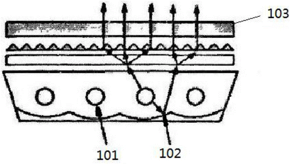
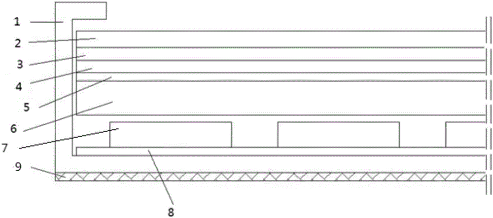
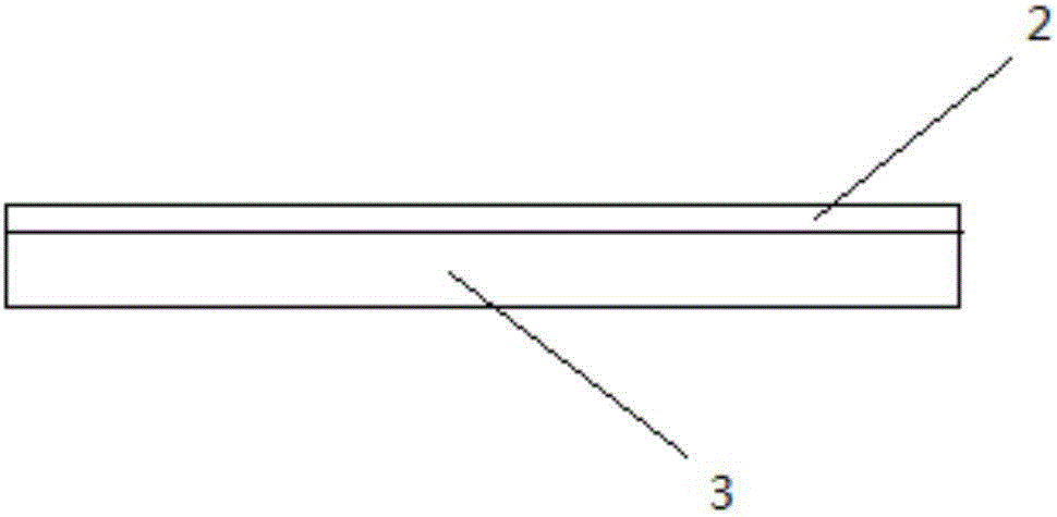
[0047] see figure 2 . like figure 2 As shown, from top to bottom are: SiOx layer 2, upper prism sheet 3, lower prism sheet 4, diffusion plate 5, light guide plate 6, light source 7, flexible circuit board 8, bottom plate of backplane 1 and heat dissipation film 9. A light source 7 is set above the bottom plate of the back plate 1, a light guide plate 6 is set above the light source 7, a diffusion plate 5 is set above the light guide plate 6, and a lower prism sheet 4 and an upper prism are sequentially set above the diffusion plate 5 Sheet 3; flexible circuit board 8 is arranged between the light source 7 and the bottom plate of the backplane 1 and supplies power to the light sou...

Embodiment 2

[0053] The difference between this embodiment and embodiment 1 is only: it is about the optimized arrangement mode of the SiOx layer on the upper surface of the upper prism sheet 3, and the thickness of the SiOx layer is The thickness of the heat dissipation film is 0.05mm, while other technical features and technical problems to be solved are the same as those in Embodiment 1.

[0054] The scheme of this embodiment is: the outer edge of the thermal insulation layer is flush with the outer edge of the upper surface of the upper prism sheet, the inner edge of the thermal insulation layer is rectangular, and the four corners of the rectangle are chamfered. The advantage of this solution is that stress concentrations at the four corners of the rectangle are avoided. See Figure 7 .

Embodiment 3

[0056] The only difference between this embodiment and embodiment 1 is that it is about the optimized arrangement of the SiO layer on the upper surface of the upper prism sheet 3 , while other technical features and technical problems to be solved are the same as those of embodiment 1.

[0057] The outer edge of the thermal insulation layer is flush with the outer edge of the upper surface of the upper prism sheet, and the inner edge of the thermal insulation layer is oval. See Figure 8 .


PUM

PropertyMeasurementUnit
thicknessaaaaaaaaaa

Abstract

The invention relates to a direct-lit backlight module. The direct-lit backlight module comprises a back plate, an upper prismatic lens, a lower prismatic lens, a diffusion plate, a light guide plate, a light source and a flexible circuit board. The flexible circuit board is arranged above a bottom plate of the back plate, the light guide plate is arranged above the light source which is arranged above the flexible circuit board, and the lower prismatic lens and the upper prismatic lens are sequentially arranged above the diffusion plate which is arranged above the light guide plate. The backlight module further comprises a thermal insulation layer and a thermal radiation film, the thermal insulation layer is arranged on the upper prismatic lens, and the thermal radiation film is arranged on the lower surface of the bottom plate of the back plate. By addition of the thermal radiation film on the lower surface of the bottom plate of the back plate and addition of the thermal insulation layer on the upper prismatic lens, thermal energy generated by lighting can be quickly diffused from the back surface, and accordingly thermal radiation performance of the backlight module is greatly improved while the service life of a liquid crystal panel is prolonged.

Description

technical field [0001] The invention belongs to the technical field of liquid crystal display, and in particular relates to a direct-lit backlight module with improved heat dissipation performance. Background technique [0002] Most of the liquid crystal display devices currently on the market are backlight liquid crystal display devices, which include a housing, a liquid crystal panel disposed in the housing, and a backlight module disposed in the housing. The backlight module is an optical component that provides back light in LCD display products. Since the LCD panel itself does not emit light, the performance of the backlight module largely determines the visual sense of the display. With the improvement of liquid crystal display technology, under the trend of large size and low price, the backlight module is also developing in the direction of light weight, thinner, low power consumption, and high brightness. [0003] The structure of a traditional liquid crystal pane...

Claims


Application Information

Patent Timeline
Patent Type & Authority Applications(China)
IPC IPC(8): G02F1/13357G02F1/1333
CPCG02F1/133382G02F1/133602G02F1/133628
Inventor 陈辰
Owner WUHAN CHINA STAR OPTOELECTRONICS TECH CO LTD
Why Eureka
Try Eureka