
Short-circuit current self-driven quick switch

A fast switching, short-circuit current technology, applied in high-voltage/high-current switches, electrical switches, circuits, etc., can solve the problems of low mechanical life and many driving links, etc., so as to improve the life of the mechanism, reduce the connection links, and reduce the stress. Effect

Pending Publication Date: 2021-06-11
NAVAL UNIV OF ENG PLA
View PDF8 Cites 2 Cited by
  • Summary
  • Abstract
  • Description
  • Claims
  • Application Information

AI Technical Summary

Problems solved by technology

In addition to the repulsion coil and the repulsion disk, the traditional fast repulsion mechanism requires an additional pre-charged capacitor and its charging and discharging equipment, and an insulating pull rod is often required between the repulsion mechanism and the moving contact to ensure the effective connection between the repulsion drive circuit and the main circuit. Insulation, there are many driving links, low mechanical life and other problems

Method used


Image

  • Short-circuit current self-driven quick switch
  • Short-circuit current self-driven quick switch

Examples


Embodiment Construction

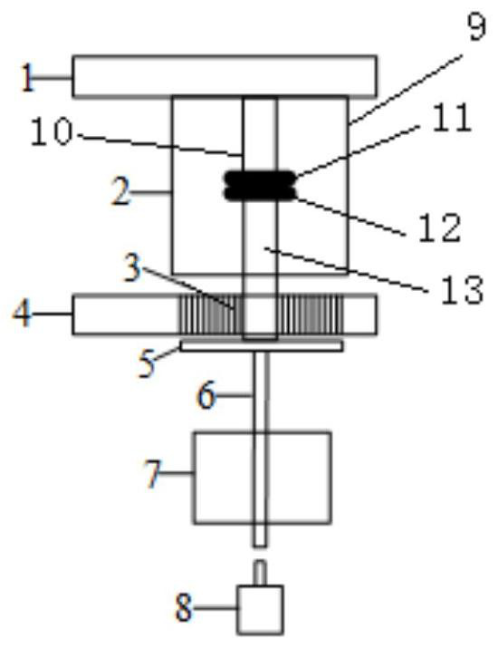
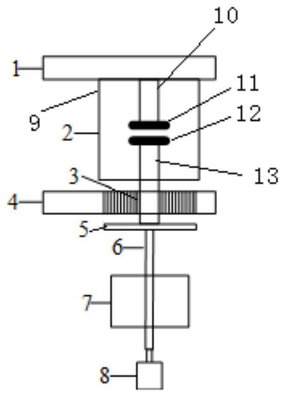
[0011] Embodiments of the present invention will be described below in conjunction with the accompanying drawings, but they are not intended to limit the present invention. figure 1 It is a schematic diagram of the fast switch closing position of the present invention, figure 2 It is a schematic diagram of the opening position of the quick switch of the present invention.

[0012] Such as figure 1 The short-circuit current self-driven fast switch includes the upper outgoing busbar 1, the lower outgoing busbar 4, the contact system 2 arranged between the upper outgoing busbar 1 and the lower outgoing busbar 4, and integrated in the lower outgoing busbar 4 The repulsion coil 3 on the top, the repulsion disk 5 arranged directly below the repulsion coil 3, the insulating connecting shaft 6 fixed on the repulsion disk 5, the holding mechanism 7 and the buffer 8, the bottom end of the insulating connecting shaft 6 passes through the holding mechanism 7 and the buffer 8 are arrang...


PUM


Abstract

The invention discloses a short-circuit current self-driven quick switch. The switch comprises an upper wire outlet busbar, a lower wire outlet busbar, a contact system arranged between the upper wire outlet busbar and the lower wire outlet busbar, a repulsive force coil integrated on the lower wire outlet busbar, a repulsive force disc arranged under the repulsive force coil, an insulation connecting shaft with the top end fixed to the repulsive force disc, a holding mechanism and a buffer. The bottom end of the insulation connecting shaft penetrates through the holding mechanism and is arranged to correspond to the buffer, and the repulsive force coil is connected into a main loop in series and forms a through-flow loop together with the upper outgoing line busbar and the lower outgoing line busbar. The repulsive force coil is connected into the main loop in series, the rapid repulsive force opening is achieved through the short-circuit current self-driving under the fault working condition, a driving capacitor bank and a charging and discharging component thereof are omitted, the mechanism is simpler, waiting for an external instruction is not needed, and the opening response is faster and more reliable; and the repulsive force disc can be directly connected with the moving contact, thereby reducing connection links, further shortening response time delay, reducing stress of the insulation pull rod, and prolonging service life of the mechanism.

Description

technical field [0001] The invention belongs to the technical field of switching appliances, and in particular relates to a short-circuit current self-driven fast switch. Background technique [0002] The electromagnetic repulsion mechanism made by the eddy current principle has the characteristics of short response time and fast opening speed, and has broad applications in many fields such as power system fault current limiting, DC circuit breakers, and phase-controlled vacuum switches. The traditional electromagnetic repulsion mechanism usually uses a pre-charged capacitor group to discharge to the repulsion coil to generate a pulse current, so that an eddy current is induced in the nearby repulsion plate and a large electromagnetic force is generated, and the repulsion plate drives the connecting rod to move to realize the rapid switch. brake. In addition to the repulsion coil and the repulsion disk, the traditional fast repulsion mechanism requires an additional pre-cha...

Claims


Application Information

Patent Timeline
Patent Type & Authority Applications(China)
IPC IPC(8): H01H33/666
CPCH01H33/666
Inventor 刘路辉付立军吴楠薛杰马凡纪锋熊又星
Owner NAVAL UNIV OF ENG PLA
Learn More