
Device with thermoelectric power generation and heat dissipation functions and thermoelectric power generation method

A technology of thermoelectric power generation and thermoelectric power generation modules, which is applied in the direction of generators/motors, circuits, electrical components, etc., can solve the problems of no obvious help in airflow organization optimization, inability to efficiently use thermoelectric power generation, and difficulty in quickly draining fluids, etc., to achieve improved Heat dissipation effect, small resistance, easy management and use

Pending Publication Date: 2021-06-11
CHONGQING UNIV
View PDF0 Cites 0 Cited by
  • Summary
  • Abstract
  • Description
  • Claims
  • Application Information

AI Technical Summary

Problems solved by technology

[0003] In the thermoelectric power generation device in the prior art, the semiconductor power generation chips are all sheet-like structures. Although they have strong mobility and can be used in most occasions, for situations that require rapid heat dissipation, the sheet-like power generation chips are thin and cannot Rapid heat dissipation, resulting in small temperature difference between the cold and hot ends, making it impossible to efficiently use the temperature difference to generate electricity; in addition, the cold and hot ends of the thermoelectric power generation device are close to each other, resulting in a small temperature difference and low power generation efficiency
[0004] For heat sinks, there are mainly the following types in the prior art: ① flat-fin heat sink can ensure heat transfer performance by increasing the heat transfer area, but it does not significantly help the optimization of airflow organization; ② corrugated herringbone heat sink It can increase the pressure bearing and improve the heat transfer performance, but the enhanced turbulence makes it difficult to quickly remove the fluid; ③Sinusoidal, triangular and other heat sinks can enhance the eddy current disturbance and heat transfer effect, but it is difficult to quickly remove the fluid. The resistance also increased to some extent

Method used


Image

  • Device with thermoelectric power generation and heat dissipation functions and thermoelectric power generation method
  • Device with thermoelectric power generation and heat dissipation functions and thermoelectric power generation method
  • Device with thermoelectric power generation and heat dissipation functions and thermoelectric power generation method

Examples


Embodiment 1

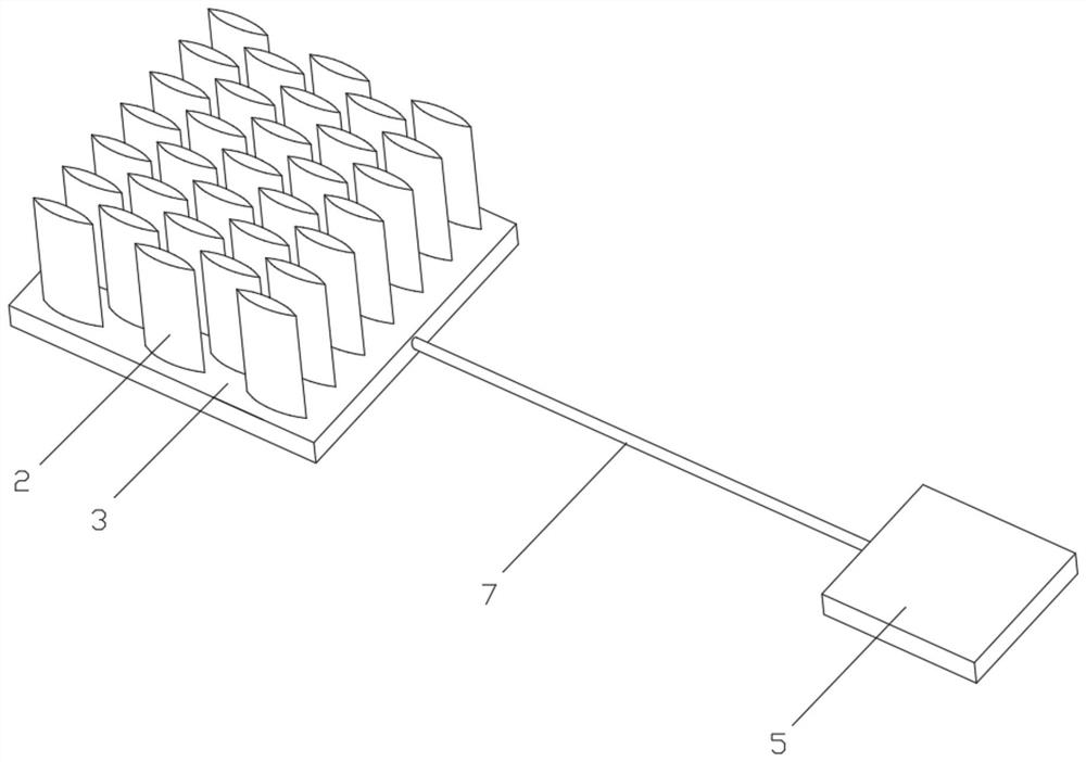
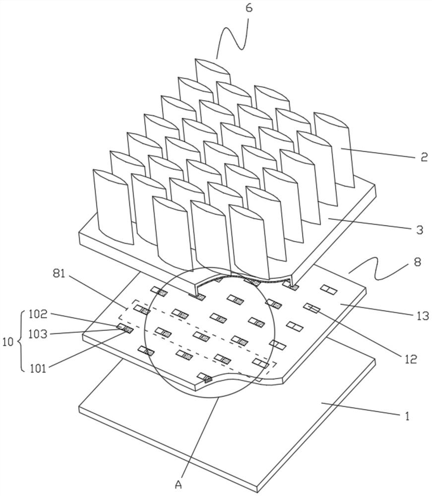
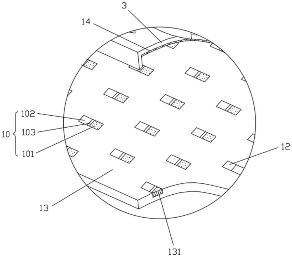
[0036] refer to Figure 1 to Figure 6 , a device with thermoelectric power generation and heat dissipation functions of the present invention includes a high-temperature end heat conduction module, a low-temperature end heat conduction module, a short-distance thermoelectric power generation module and a long-distance thermoelectric power generation module.

[0037] The heat conduction module at the high temperature end includes a heat conduction layer 1 at the high temperature end for abutting against a high temperature object, and a set of cooling ribs arranged on the heat conduction layer 1 at the high temperature end. The heat conduction layer 1 at the high temperature end is a heat conduction silica gel layer. The heat dissipation fin group includes a plurality of heat dissipation fins 2, the heat dissipation fins 2 are cylinders with a streamlined cross section, and the plurality of heat dissipation fins are arranged in a rhombus staggered manner, and the heat dissipatio...

Embodiment 2

[0044] refer to Figure 7 and Figure 8 , The difference between this embodiment and Embodiment 1 is that: the metal insulating substrates 13 of the hot end module 8 and the cold end module 9 are provided with several wire channels 15 for embedding wires 7 . Several heat dissipation fins 2 of the heat dissipation fin group are connected as a whole through an insulating heat conducting plate, and the heat dissipation fins 2 are bonded to the insulating heat conducting plate. The metal insulating substrate 13 of the hot end module 8 is closely connected between the high temperature end heat conducting layer 1 and the insulating heat conducting plate.


PUM


Abstract

The invention relates to a device with thermoelectric power generation and heat dissipation functions and a thermoelectric power generation method. The device with the thermoelectric power generation and heat dissipation functions comprises a high-temperature end heat conduction module, a low-temperature end heat conduction module, a short-distance thermoelectric power generation module and a long-distance thermoelectric power generation module, wherein the high-temperature end heat conduction module comprises a high-temperature end heat conduction layer and a heat dissipation fin group, the low-temperature end heat conduction module comprises a low-temperature end heat conduction layer, the short-distance thermoelectric power generation module is arranged in the heat dissipation fin group, and the long-distance thermoelectric power generation module comprises a hot end module arranged on the high-temperature end heat conduction layer and a cold end module arranged on the low-temperature end heat conduction layer. According to the invention, the thermoelectric power generation device and the rapid heat dissipation device are integrated, so that heat exchange can be enhanced through the heat dissipation fins while thermoelectric power generation is utilized, the heat dissipation effect is good, and instruments and equipment can be better protected; and the short-distance thermoelectric power generation module and the long-distance thermoelectric power generation module are arranged, so that thermal energy can be fully utilized to drive thermoelectric power generation, and the power generation efficiency is improved.

Description

technical field [0001] The invention relates to the technical field of heat dissipation and power generation utilization, in particular to a device with thermoelectric power generation and heat dissipation functions and a thermoelectric power generation method. Background technique [0002] According to the principle of thermoelectric power generation, when two metal conductors (or semiconductors) with different free electron densities (or carrier densities) in a temperature difference environment contact each other, the electrons on the contact surface diffuse from high concentration to low concentration, and the electrons The diffusion rate is proportional to the temperature difference across the contact area. Therefore, as long as the temperature difference between the two contacting conductors is maintained, electrons can continue to diffuse, and a stable voltage will be formed between the other two terminals of the two conductors to realize thermoelectric power generati...

Claims


Application Information

Patent Timeline
Patent Type & Authority Applications(China)
IPC IPC(8): H02N11/00H01L35/10H01L35/32H05K7/20H10N10/17H10N10/82
CPCH02N11/002H05K7/20445H10N10/82H10N19/101
Inventor 黄海林杜建建马弋涵白雪莲王梦真傅佳键林康志范鸿瑜
Owner CHONGQING UNIV
Learn More