Controlling wind turbines in presence of wake implications
What is Al technical title?
Al technical title is built by PatSnap Al team. It summarizes the technical point description of the patent document.
A wind turbine and wake technology, which is applied in the directions of wind turbines, wind turbine control, engine control, etc., to reduce wear, reduce wake losses, and increase power generation.
Pending Publication Date: 2021-06-11
SIEMENS GAMESA RENEWABLE ENERGY AS
View PDF1 Cites 0 Cited by
Summary
Abstract
Description
Claims
Application Information
AI Technical Summary
This helps you quickly interpret patents by identifying the three key elements:
Problems solved by technology
Method used
Benefits of technology
Problems solved by technology
[0009] In general, it must also be noted that all yaw movements generate mechanical loads or stresses on components such as bearings, and high yaw control activity may have a negative impact on these components in terms of their service life or maintenance cycles
Method used
Image
Click on the blue label to locate the original text in one second.
Reading with bidirectional positioning of images and text.
Examples
Embodiment Construction
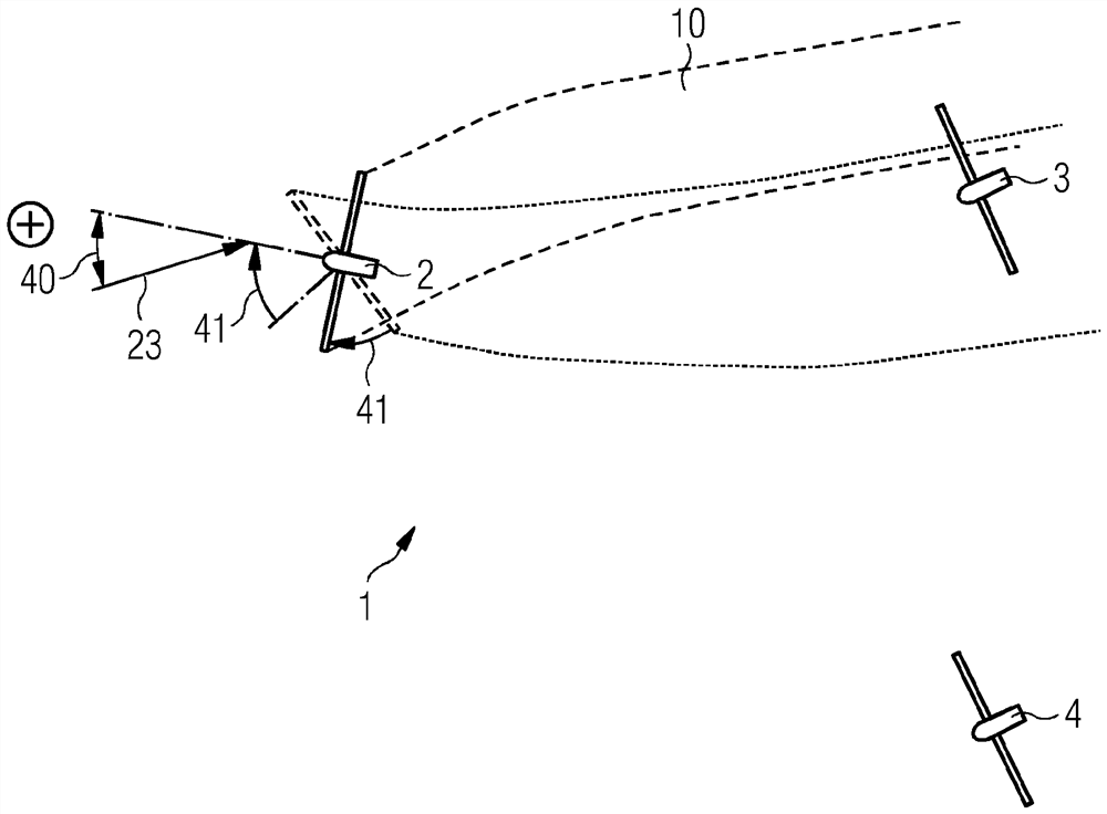
[0090] exist figure 1 , schematically shows a wake generated by a wind turbine rotor as viewed from above. This means that the direction of view is defined as looking from the air above the wind turbine towards the ground or water on which the wind turbine stands. for another Figure 2-6 Also like this.
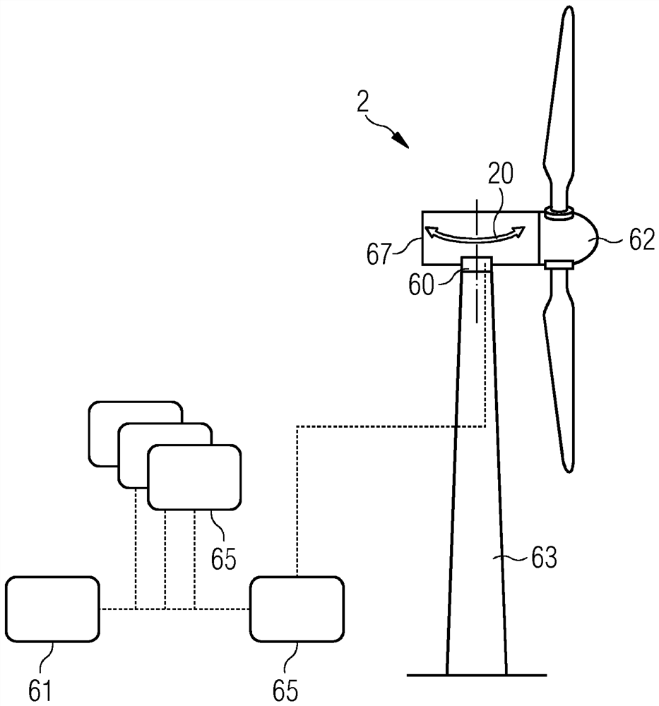
[0091] exist figure 1 And in the further figures, a wind farm 1 is shown abstractly, having at least a first wind turbine 2 and a second wind turbine 3 . Wind farms usually also include figure 1 Other wind turbines shown in .
[0092] The first wind turbine 2 is shown very abstractly with a rotor 22 which is only depicted as a straight line from the top, which defines an area 64 which is passed through or covered by the rotor blades when rotating. Another element of the abstract depiction of the wind turbine is the hub 62 and the nacelle 67 . Hub 62 and nacelle 67 are placed in the figure 1 On the tower shown in , and this orientation is into the wind, during operatio...
PUM
Abstract
The invention is directed to a wind park, a wind park controller, and a method for controlling a first wind turbine (2, 2') of a plurality of wind turbines (2,3,4,...) of a wind park (1), wherein a second wind turbine (3, 3') of the plurality of wind turbines (2,3,4,...) can be affected by a wake region (10) caused by the first wind turbine (2, 2') which is positioned upstream of the second wind turbine (3, 3'). A current yaw state is determined, wherein the current yaw state is selected from at least one of: a) an actual rotor yaw misalignment angle (20) of the first wind turbine (2, 2'), wherein the actual rotor yaw misalignment angle (20) is defined as an angle between a rotating axis (21) of a rotor (22) of the first wind turbine (2, 2') and a current wind direction (23) at the rotating axis (21) upstream of the first wind turbine (2, 2'), b) an identifier representing whether the actual rotor yaw misalignment angle (20) is either in a range of positive yaw misalignment angles (24) or alternatively of negative yaw misalignment angles (25). Further, wind conditions are determined which are indicative of the potential wake inducement on the second turbine (3, 3'), such as wind direction. A rotor yaw offset angle set point (40) for the first wind turbine (2, 2') is defined, following a hysteresis (50) based on the current yaw state, the wind conditions, and at least one yaw angle hysteresis switching threshold (51, 52). Thereby immediate consecutive switching between a range of positive yaw offset angles and negative yaw offset angles is avoided.
Description
technical field [0001] The invention relates to a method and a wind park controller for controlling at least one wind turbine in a wind park comprising a plurality of wind turbines, and also to a wind park comprising the wind park controller. Background technique [0002] A wind farm includes a plurality of wind turbines. Depending on the current wind direction, some wind turbines are located downstream of other wind turbines. Upstream wind turbines may reduce the wind speed and wind energy experienced by downstream wind turbines. At downstream wind turbines, wind turbulence may also increase. The leeward region downstream or behind the upstream wind turbine may also be referred to as the wake region of the upstream wind turbine, or simply the wake. [0003] To reduce production losses caused by wind turbine wakes in wind farms, optimized blade pitch, rotor speed, power production set point, rotor pitch and / or yaw offset or other controls on the wind turbine can be used ...
Claims
Application Information
Patent Timeline
Application Date:The date an application was filed.
Publication Date:The date a patent or application was officially published.
First Publication Date:The earliest publication date of a patent with the same application number.
Issue Date:Publication date of the patent grant document.
PCT Entry Date:The Entry date of PCT National Phase.
Estimated Expiry Date:The statutory expiry date of a patent right according to the Patent Law, and it is the longest term of protection that the patent right can achieve without the termination of the patent right due to other reasons(Term extension factor has been taken into account ).
Invalid Date:Actual expiry date is based on effective date or publication date of legal transaction data of invalid patent.