Electromagnetic driving galvanometer for reducing rocking motion

A technology of electromagnetic drive and rocking motion, applied in the direction of optical components, optics, instruments, etc., can solve the problems of poor driving effect, achieve the effects of less energy loss, high energy utilization rate, and improved stability

Pending Publication Date: 2019-04-26
XI AN ZHISENSOR TECH CO LTD
View PDF9 Cites 3 Cited by
  • Summary
  • Abstract
  • Description
  • Claims
  • Application Information

AI Technical Summary

Problems solved by technology

However, the micro-vibration mirror uses soft magnetic materials, and the driving effect is poor.

Method used


Image

  • Electromagnetic driving galvanometer for reducing rocking motion
  • Electromagnetic driving galvanometer for reducing rocking motion
  • Electromagnetic driving galvanometer for reducing rocking motion

Examples


Embodiment 1

[0048] From Figure 4 It can be seen that the electromagnetically driven oscillating mirror in this embodiment mainly includes an electromagnetic oscillating mirror chip 31, a structure 32 and a driving magnetic circuit 34. Among them, the structure 32 supports and fixes the electromagnetic vibrating mirror chip 31 and the driving magnetic circuit 32, combines the electromagnetic vibrating mirror chip 31 and the driving magnetic circuit 32, and ensures the relative position of the two, and provides the external interface of the electromagnetic vibrating mirror at the same time (including mechanical interfaces or fixed electrical components or interfaces).

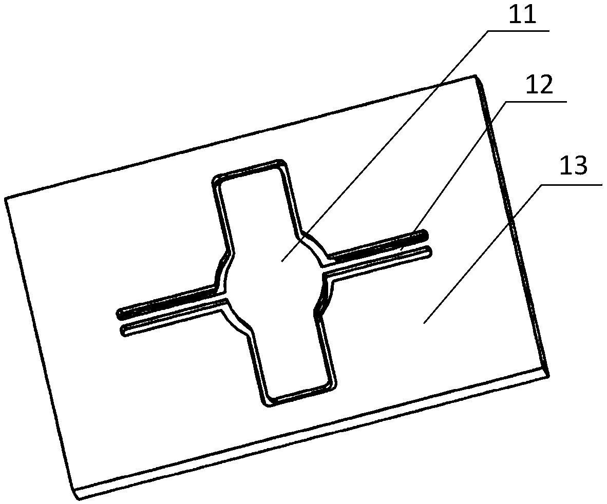
[0049] The electromagnetic vibrating mirror chip 31 of this embodiment includes a movable mirror 11, a torsion beam 12 and a fixed frame 13, and the movable mirror 11 is fixed on the fixed frame 13 through the torsion beam 12. The opposite side of the movable mirror 11 is provided with a magnetic material 14 and a reinforcin...

Embodiment 2

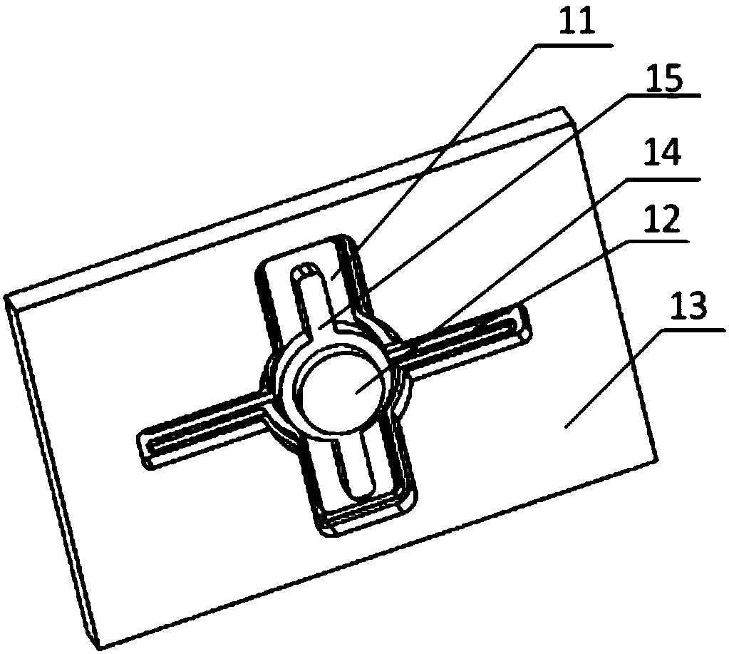
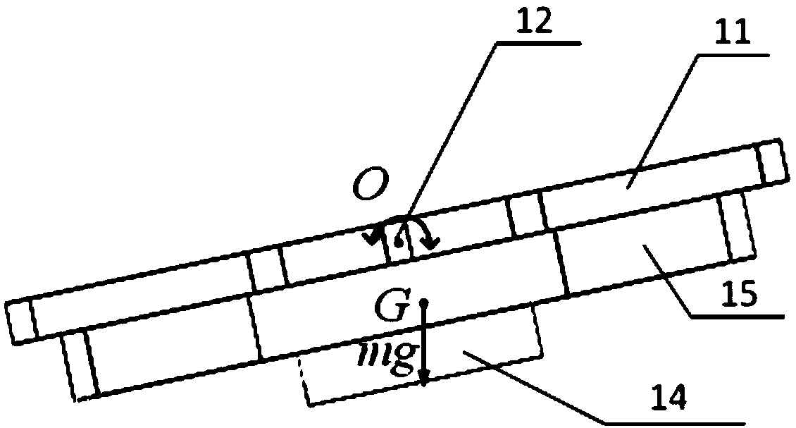
[0059] On the basis of Embodiment 1, this embodiment discloses an electromagnetically driven oscillating mirror, from Figure 3a and Figure 3b It can be seen that the electromagnetically driven oscillating mirror in this embodiment includes a movable mirror 11, a torsion beam 12, a fixed frame 13, a reinforcing rib 15 on the opposite side of the mirror, and a magnetic material 14, and the movable mirror 11 is fixed on the fixed frame 13 by the torsion beam 12. . In this embodiment, the center of the reinforcing rib 15 is ring-shaped, and is arranged on the opposite side of the movable mirror 11. The magnetic material 14 passes through the central ring of the reinforcing rib 15 and is pasted on the opposite side of the movable mirror 11, and the reinforcing rib 15 limits the magnetic material 14. . In other embodiments, the reinforcing rib can be in any other shape, and the magnetic material can be pasted on the surface of the reinforcing rib.

[0060] From Figure 3c It ...

Embodiment 3

[0062] Between the electromagnetic oscillating mirror chip 31 and the structure 32, due to different materials and different thermal expansion coefficients, the galvanizing mirror structure will generate stress when the system working environment temperature changes, resulting in changes in the working performance of the galvanizing mirror, such as resonance frequency, etc., from Figure 4 It can be seen that in this embodiment, on the basis of the first embodiment, a stress buffering structure 33 is provided between the electromagnetic vibrating mirror chip 31 and the structure body 32 . The stress buffering structure 33 can be positioned and fixed on the structure 32, and the electromagnetic vibrating mirror chip 31 can be positioned and fixed on the stress buffering structure 33; Thermal stress problem caused by different coefficients of thermal expansion, the stress buffering structure 33 material should be a material close to the thermal expansion coefficient of the electr...


PUM


Abstract

The invention belongs to the field of micro-optoelectronics, and particularly relates to an electromagnetic driving galvanometer for reducing the rocking motion. The galvanometer includes an electromagnetic galvanometer chip, a structure body and a driving magnetic circuit; the structure body is used for fixing the electromagnetic galvanometer chip and the driving magnetic circuit; the electromagnetic galvanometer chip includes a movable structure, a torsion beam and a fixing frame, and the movable structure is fixed on the fixing frame through the torsion beam; the driving magnetic circuit isused for driving the movable structure to move; the movable structure includes a movable mirror and a magnetic material set on the opposite side of the movable mirror; when the movable mirror is located in a horizontal position, the center of the upper surface of the movable mirror is defined as an origin, and the Z axis is perpendicular to the movable mirror; the center of gravity of the movablestructure is on the Z axis, and the Z axis coordinate of the center of gravity of the movable structure is the same as the Z axis coordinate of the center of the torsion beam. By matching the position of the torsion beam of the galvanometer and the gravity center of the galvanometer, the deviation between the torsion beam of the galvanometer and the gravity center of the galvanometer is reduced,and the rocking motion of the galvanometer is reduced.

Description

technical field [0001] The invention belongs to the field of micro-optomechanics, and in particular relates to a MEMS micro-vibration mirror, especially a micro-vibration mirror based on electromagnetic drive. Background technique [0002] Compared with traditional beam deflection elements, MEMS galvanometers have the advantages of miniaturization, low energy consumption, fast response, easy integration, and long life. With the development of artificial intelligence and the demand for high-precision, miniaturized, and low-cost devices, MEMS Galvanometers shine in the fields of three-color laser projection, laser radar, and 3D measurement. At the same time, the performance requirements for galvanometers are also further improved. [0003] Electromagnetic drive has the advantages of linear response, large driving force, fast response speed, low driving voltage, and insensitivity to size. It is one of the most commonly used driving methods for micro-vibrators. Electromagnetica...

Claims


Application Information

Patent Timeline
Patent Type & Authority Applications(China)
IPC IPC(8): G02B26/08
CPCG02B26/085
Inventor 宋秀敏夏长锋游桥明乔大勇何伟
Owner XI AN ZHISENSOR TECH CO LTD
Why Eureka
Try Eureka