Cleaning barrel of cleaning device

A cleaning device and cleaning barrel technology, applied in the field of cleaning barrels, can solve the problems of high mop barrel height, inconvenient packaging and transportation, and large floor space, and achieve the requirements of reducing the height of the barrel body, facilitating product packaging and transportation, and reducing the lifting stroke Effect

Active Publication Date: 2021-06-15
JIAXING JACKSON TRAVEL PROD CO LTD
View PDF9 Cites 0 Cited by
  • Summary
  • Abstract
  • Description
  • Claims
  • Application Information

AI Technical Summary

Problems solved by technology

[0004] In order to achieve a better mopping effect and improve mopping efficiency, it is generally desired that the length of the flat mop board is relatively long. When inserting into the extruding device at the extrusion port during cleaning and extruding, if the length of the flat mop plate is longer, the height of the corresponding mop bucket will be higher, which will cause the mop bucket to be bulky and inconvenient for packaging and transportation.
When the mop is being cleaned, the mop is inserted into the mop bucket for cleaning. The mop bucket needs to be filled with water, and then the mop is inserted into the mop bucket for cleaning. In order to clean all the wipes on the mop, the height of the mop bucket must be greater than It is equal to the length of the mop head, which leads to making the mop bigger and improving the efficiency of mopping the floor, which will inevitably lead to a higher height of the mop bucket. On the one hand, it occupies a large area and requires a lot of water. It is necessary to move up and down at least twice the length of the mop head to complete the cleaning, which causes inconvenience for users. Therefore, the improvement of mopping efficiency and the advantages of light mop cleaning can only be selected. The fundamental reason is that the cleaning of the mop When the cleaning water cannot be raised above the liquid level, the mop head can only be completely immersed in the liquid level to complete the cleaning

Method used


Image

  • Cleaning barrel of cleaning device
  • Cleaning barrel of cleaning device
  • Cleaning barrel of cleaning device

Examples


Embodiment 1

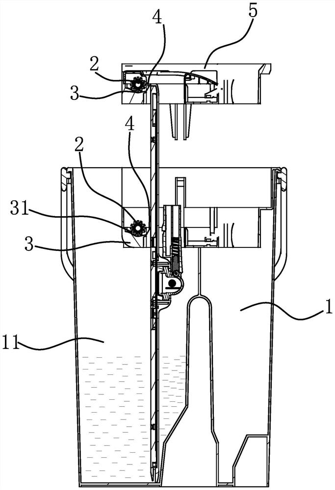
[0051] Such as Figure 1-3 As shown, the cleaning barrel of the cleaning device includes a barrel body 1, the barrel body 1 is provided with an opening, the cleaning device can enter the barrel body 1 along the opening of the barrel body 1, and the barrel body 1 is provided with a A water supply structure that wets at least a part of the cleaning device that extends into the barrel body 1. The water supply mechanism is an accommodating chamber 11 disposed in the barrel body 1, and the accommodating chamber 11 has a water storage function. The bucket body 1 is provided with a transfer mechanism that uses the movement of the cleaning device to lift the liquid in the wet part of the cleaning device and transfer it to the non-wet part of the cleaning device. The element 2 can transfer the liquid from the wetted part of the cleaning device to the water-carrying part 2 and release it to the non-wetted part of the cleaning device. The water-carrying part 2 is a roller or a sponge, e...

Embodiment 2

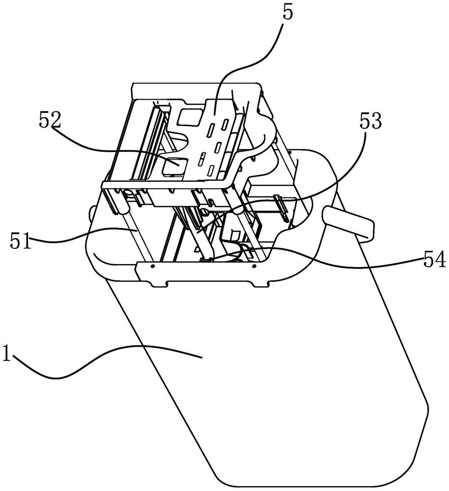
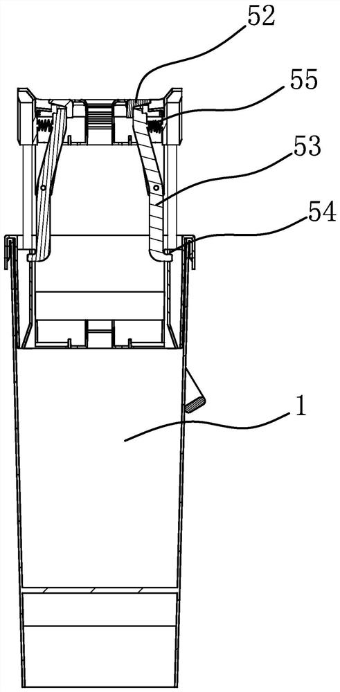
[0057] The principle of the transfer mechanism of this embodiment is the same as that of Embodiment 1, the difference lies in the water supply structure, such as Figure 4-5 As shown, in this embodiment, the water supply mechanism is a water outlet device arranged in the barrel body 1, and the water outlet device includes a water outlet 6, and the water outlet direction of the water outlet 6 faces the cleaning device. The water on the water outlet 6 flows to the cleaning device. The water can flow out from the water storage bucket 7, or it can be an external water source, or even manually poured water. In this embodiment, the water outlet device also includes a The water storage bucket 7 is connected with the water outlet 6, and the water outlet 6 is provided with a water outlet valve 71 for controlling the opening and closing of the water outlet 6. The barrel body 1 is provided with a link mechanism, and the link mechanism controls the on-off of the water outlet valve 71 . T...

Embodiment 3

[0061] Such as Figure 6-7 As shown, the working principle of this embodiment is basically the same as that of Embodiment 1, the difference is that the transfer mechanism includes a scraper 10, and the scraper 10 can scrape off and release the liquid in the wetted part of the cleaning device. Clean the unwetted part of the device.

[0062]The scraper 10 includes a wiper part 4 arranged in the barrel body 1 and a water guide part arranged under the scraper, the wiper part 4 can scrape off the liquid in the wet part of the cleaning device and pass it through the water guide Divert the flow to the unwetted part of the cleaning device.

[0063] The wiper part 4 is movably connected to the bucket body 1, and the wiper part 4 does not play the role of wiping when the cleaning device rises, and the scraper 10 plays the role of wiping when the cleaning device goes down.

[0064] When in use, the wetted part of the cleaning device is lifted up, and the scraper 10 rotates until the wi...


PUM


Abstract

The invention relates to a cleaning barrel of a cleaning device and belongs to the technical field of cleaning. A problem that in the prior art, a cleaning barrel needs to be higher than a cleaning device is solved. The cleaning barrel of the cleaning device comprises a barrel body, wherein an opening is formed in the barrel body, the cleaning device can enter the barrel body along the opening of the barrel body, and a water feeding structure capable of wetting at least one part of the cleaning device stretching into the barrel body is arranged in the barrel body; the barrel body is provided with a transferring mechanism which lifts and transfers liquid of a wetting part of the cleaning device to the non-wetting part of the cleaning device through movement of the cleaning device. The cleaning barrel is advantaged in that the transfer mechanism is arranged, power is provided through vertical movement of the cleaning device, liquid of the wetted part of the cleaning device is transferred to the non-wetted part, the requirement for the height of the water level is lowered, and therefore the height of the barrel can be lowered.

Description

technical field [0001] The invention belongs to the technical field of cleaning tools and relates to a cleaning barrel of a cleaning device. Background technique [0002] Mops on the market are generally divided into flat mops, cotton yarn mops, collodion mops, etc., and their function is to clean up the stains on the ground through the mop or mop head, and then clean the mop. For a flat mop, it is generally equipped with a mop bucket for cleaning the mop. The flat mop includes a mop rod and a flat mop board that is movably connected to the mop rod. Wipes are arranged on the flat mop board; Squeeze device, when cleaning and squeezing water, rotate the flat mop board to the state where it can be cleaned and squeezed water; the flat mop board is relatively moved and squeezed between the extrusion port extrusion device to move and squeeze the wiper and squeeze water. [0003] There are two types of squeeze flat cleaning tools, one is a single-barrel squeeze flat cleaning tool...

Claims


Application Information

Patent Timeline
Patent Type & Authority Applications(China)
IPC IPC(8): A47L13/58A47L13/60
CPCA47L13/58A47L13/60
Inventor 朱雪林宋潘维池丹俊甘宏亮姚嘉斌
Owner JIAXING JACKSON TRAVEL PROD CO LTD
Why Eureka
Try Eureka