City management system based on big data
A technology of urban management and big data, applied in the field of urban management system based on big data, can solve problems such as hidden dangers of personal safety, turbid monitoring of road information viewing, urban traffic operation obstacles, etc., to reduce the burden and increase the frequency of wiping.
- Summary
- Abstract
- Description
- Claims
- Application Information
AI Technical Summary
Problems solved by technology
Method used
Image
Examples
Embodiment 1
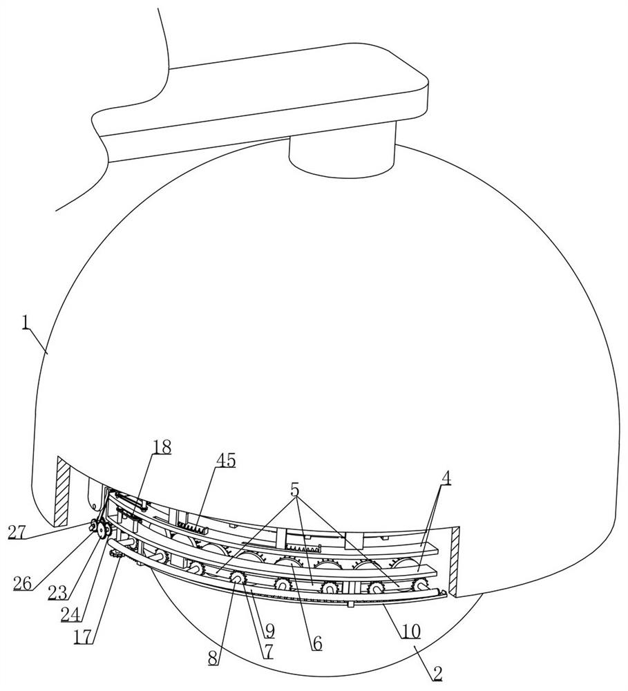
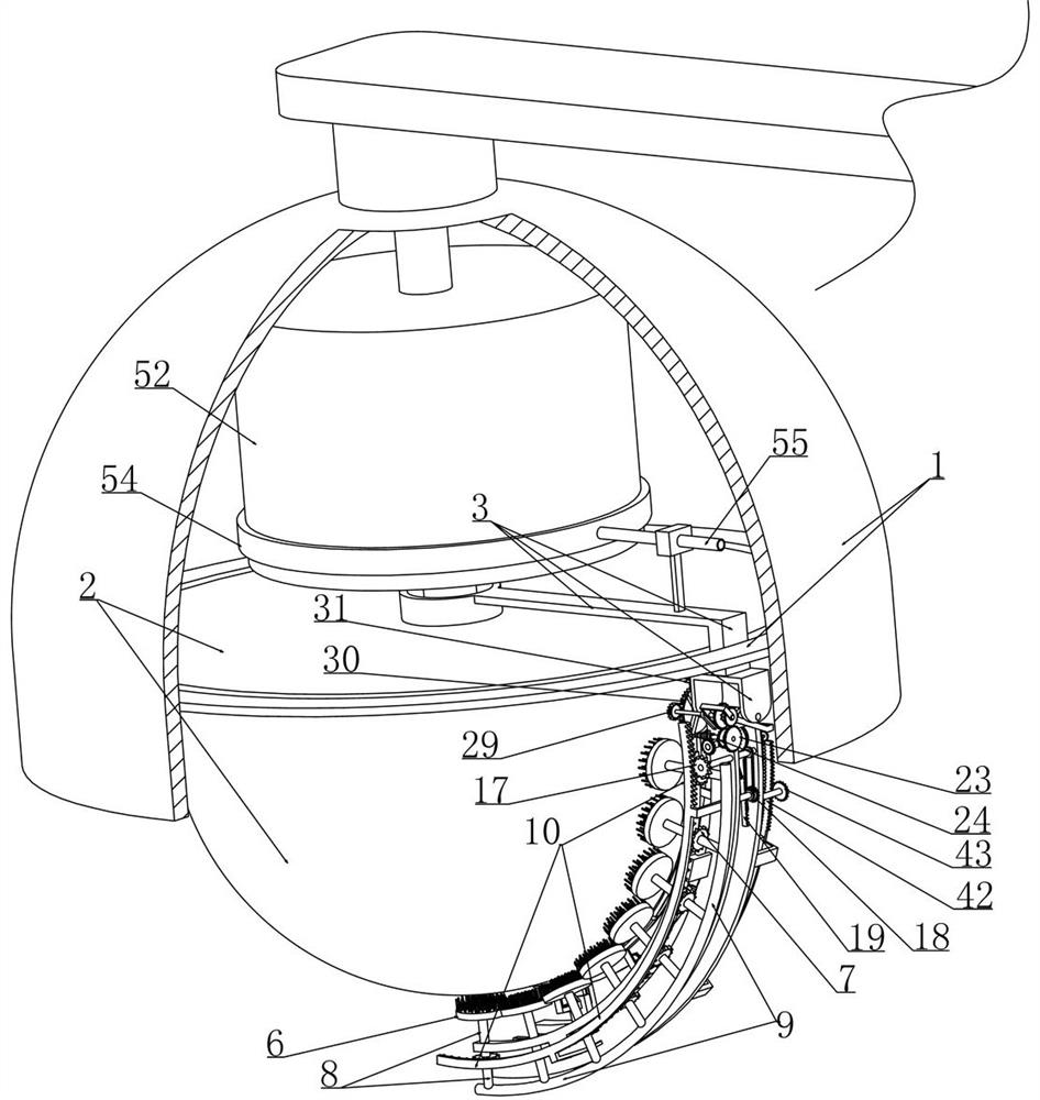
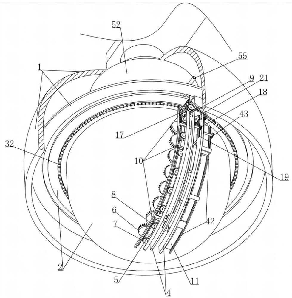
[0038] Embodiment 1, this embodiment provides a city management system based on big data, refer to the appendixfigure 1 As shown, the protective cover 1 is enclosed and the monitoring probe 2 is installed in the protective cover 1. The protective cover 1 is set to a hemispherical shape and the monitoring probe 2 is installed at the bottom end of the hemisphere, as shown in the appendix. figure 2 As shown, the monitoring probe 2 is provided with a wide-angle camera inside and a hemispherical transparent glass cover (or transparent plastic cover) is provided outside. An L-shaped rod 3 is coaxially rotated on the upper end face, and the L-shaped rod 3 is placed outside the protective cover 1, and an arc-shaped frame 4 matched with the monitoring probe 2 is rotated and installed (there is a The annular hole that fits with the vertical part of the L-shaped rod 3, as shown in the attached Figure 4 shown), the arc frame 4 and the hemispherical cover of the monitoring probe 2 are ar...
Embodiment 2
[0046] Example 2, on the basis of Example 1, with reference to the attached Figure 10 As shown, the end face ring gear 10 is meshed with a transmission gear 17 rotatably mounted on the arc-shaped frame 4 and the transmission gear 17 is connected with a reciprocating gear 18 rotatably installed on the arc-shaped frame 4 through the pulley set, along with the arc-shaped frame 4 The rotation of the drive device drives the worm gear 22 through the speed regulating device, and the worm gear 22 drives the cam plate 21 to rotate. To achieve the effect of driving the reciprocating rack 19 to reciprocate, refer to the appendix Figure 9 As shown, it is a schematic diagram of the installation relationship with the connecting rod 20 when one side wall of the cam plate 21 is deleted, that is, the rotating installation part of the connecting rod 20 and the cam plate 21 is not concentric with the rotating part of the cam plate 21, and with the reciprocating rack The reciprocating movement o...
Embodiment 3
[0047] Example 3, on the basis of Example 2, with reference to the attached Figure 9 As shown, a large gear 23 and a pinion 24 are installed coaxially on the arc-shaped frame 4 and are driven by the worm in the worm gear 22. A mounting frame 25 is fixed on the arc-shaped frame 4, and the mounting frame 25 is coaxially mounted. A first gear 26 and a second gear 27 meshing with the large gear 23 and the pinion 24 are installed at intervals. attached image 3 As shown, the driving device includes an end face gear 32 that is coaxially installed on the upper end face of the monitoring probe 2, as shown in the attached figure 2 As shown, the end gear 32 is meshed with the traveling gear 31 which is rotatably mounted on the L-shaped rod 3. When the L-shaped rod 3 rotates, the cooperation between the end gear 32 and the traveling gear 31 can drive the traveling gear 31 to rotate and pass the The outer ring gear 30 meshing with it drives the transition gear 29 to rotate, as shown i...
PUM
 Abstract
Description
Claims
Application Information
 - R&D
- Intellectual Property
- Life Sciences
- Materials
- Tech Scout
- Unparalleled Data Quality
- Higher Quality Content
- 60% Fewer Hallucinations
Browse by: Latest US Patents, China's latest patents, Technical Efficacy Thesaurus, Application Domain, Technology Topic, Popular Technical Reports.
© 2025 PatSnap. All rights reserved.Legal|Privacy policy|Modern Slavery Act Transparency Statement|Sitemap|About US| Contact US: help@patsnap.com


