Rapid cutting and separating device

A separation device and fast cutting technology, applied in shearing devices, attachment devices of shearing machines, removing smoke and dust, etc., can solve the problems of metal products shaking, unable to fix metal products, and difficult to clean the table, and achieve reliable clamping and fixing, The effect of smooth cutting, ensuring cutting accuracy and work efficiency

Inactive Publication Date: 2021-06-15
无锡美高帝机械有限公司
View PDF0 Cites 2 Cited by
  • Summary
  • Abstract
  • Description
  • Claims
  • Application Information

AI Technical Summary

Problems solved by technology

[0002] The metal product industry includes structural metal product manufacturing, metal tool manufacturing, container and metal packaging container manufacturing, stainless steel and similar daily metal product manufacturing, etc. Metal products are more and more widely used in various fields of industry, agriculture and people's lives. A cutting device is needed in the processing of metal products; the existing cutting devices have some disadvantages. First, the cutting device cannot completely fix the metal products, which may cause the shaking of the metal products during the cutting process, resulting in the cutting effect of the metal products. Not good, secondly, the tabletop of the cutting device is not easy to clean after cutting metal products, in order to solve the above problems, we propose this cutting device

Method used


Image

  • Rapid cutting and separating device
  • Rapid cutting and separating device

Examples


Embodiment Construction

[0021] The present invention will be described in further detail below in conjunction with the accompanying drawings.

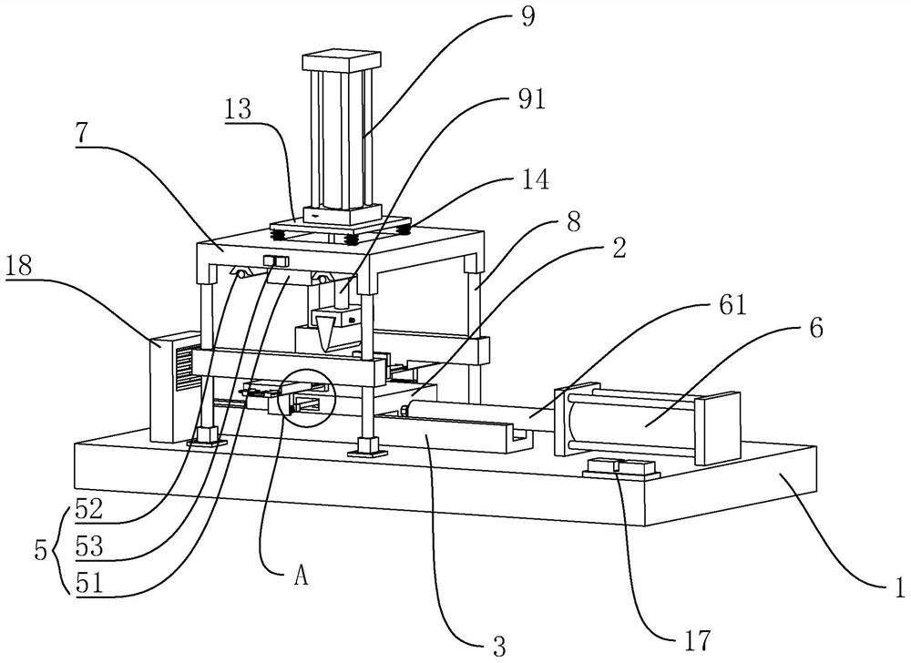
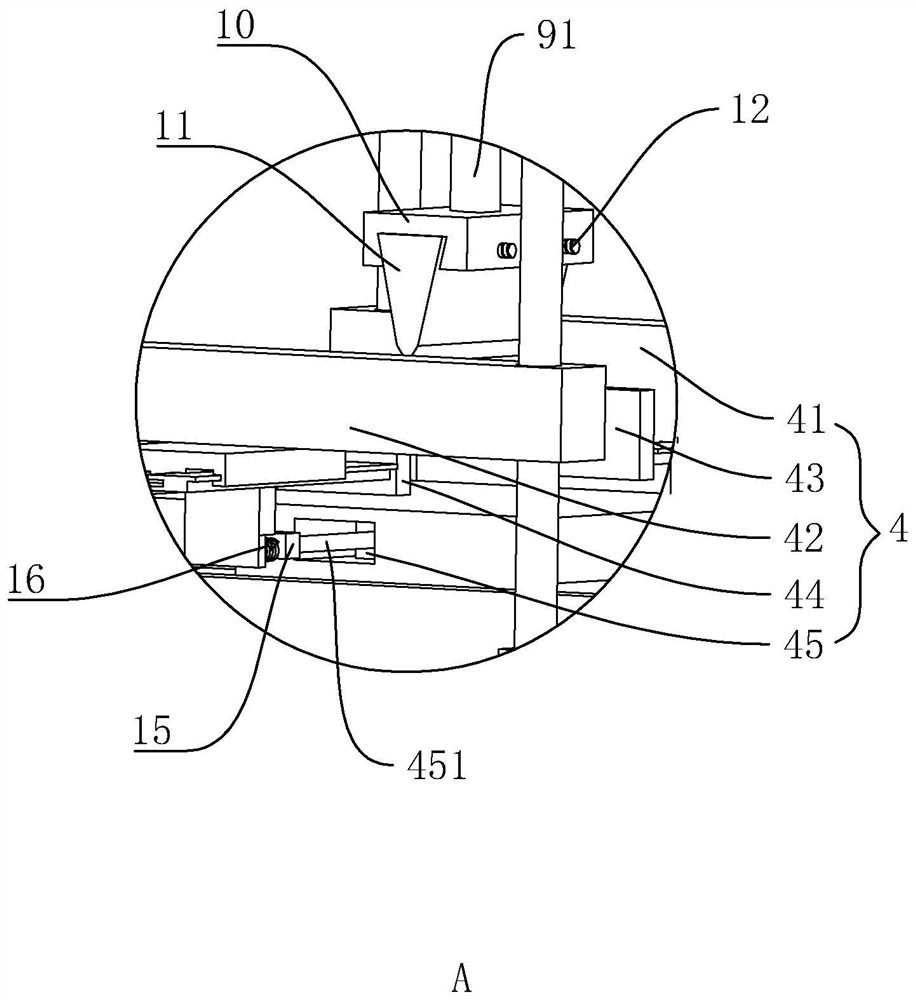
[0022] A rapid cutting and separating device, such as figure 1 , figure 2 As shown, it includes a base 1, a workbench 2 on the base 1, a slide groove 3 fixedly installed on the base 1 at the bottom of the workbench 2, a fixedly connected slider at the bottom of the workbench 2, and the slider is located in the slide groove 3 , one side of the base 1 is provided with a push cylinder 6 facing the workbench 2, and the push cylinder 6 is provided with a push rod 61, which is threadedly connected to one side of the workbench 2, and a support plate 7 is arranged above the workbench 2, and the support plate 7 is connected with the base 1 through the fixed rod 8 around, the support plate 7 is provided with a vertically downward lift cylinder 9, the bottom of the lift cylinder 9 is provided with a piston rod 91, the bottom of the piston rod 91 is equipped with a con...


PUM


Abstract

The invention discloses a rapid cutting and separating device, and aims to provide a device capable of automatically and rapidly cutting workpieces. According to the technical scheme, the device is characterized by comprising a base and a workbench arranged on the base, wherein the bottom of the workbench is provided with a sliding groove fixedly mounted on the base, a sliding block is arranged at the bottom of the workbench and located in the sliding groove, a pushing air cylinder facing the workbench is arranged on one side of the base, a pushing rod is arranged on the pushing air cylinder and is connected one side of the workbench in a threaded mode, a supporting plate is arranged above the workbench, the periphery of the supporting plate is connected with the base through fixing rods, a vertically-downward lifting air cylinder is arranged on the supporting plate, a piston rod is arranged at the bottom of the lifting air cylinder, a connecting plate is mounted at the bottom of the piston rod, and a blade is arranged at the bottom of the connecting plate in a fixedly connected mode.

Description

technical field [0001] The invention relates to the field of mechanical equipment, in particular to a quick cutting and separating device. Background technique [0002] The metal product industry includes structural metal product manufacturing, metal tool manufacturing, container and metal packaging container manufacturing, stainless steel and similar daily metal product manufacturing, etc. Metal products are more and more widely used in various fields of industry, agriculture and people's lives. A cutting device is needed in the processing of metal products; the existing cutting devices have some disadvantages. First, the cutting device cannot completely fix the metal products, which may cause the shaking of the metal products during the cutting process, resulting in the cutting effect of the metal products. Not good, secondly the table top of cutting device is not easy to clean after cutting metal products, in order to solve the above problems, we have proposed this cuttin...

Claims


Application Information

Patent Timeline
Patent Type & Authority Applications(China)
IPC IPC(8): B23D15/04B23D15/14B23D33/02B08B15/04
CPCB08B15/04B23D15/04B23D15/14B23D33/02
Inventor 惠晓春
Owner 无锡美高帝机械有限公司
Why Eureka
Try Eureka