
Speed reducing mechanism of paper splitting machine

A technology of deceleration mechanism and slitting machine, which is applied in the field of papermaking machinery, can solve problems such as poor ink application and poor printing effect, and achieve the effects of preventing light spots and pressure roller marks, good printing effect, and reducing economic losses

Inactive Publication Date: 2021-06-15
卢宏旺
View PDF0 Cites 1 Cited by
  • Summary
  • Abstract
  • Description
  • Claims
  • Application Information

AI Technical Summary

Problems solved by technology

Coated paper with light spots or roller marks will cause poor ink application during printing, or light spots and roller marks can still be seen after printing, resulting in poor printing results

Method used


Image

  • Speed reducing mechanism of paper splitting machine
  • Speed reducing mechanism of paper splitting machine
  • Speed reducing mechanism of paper splitting machine

Examples


Embodiment 1

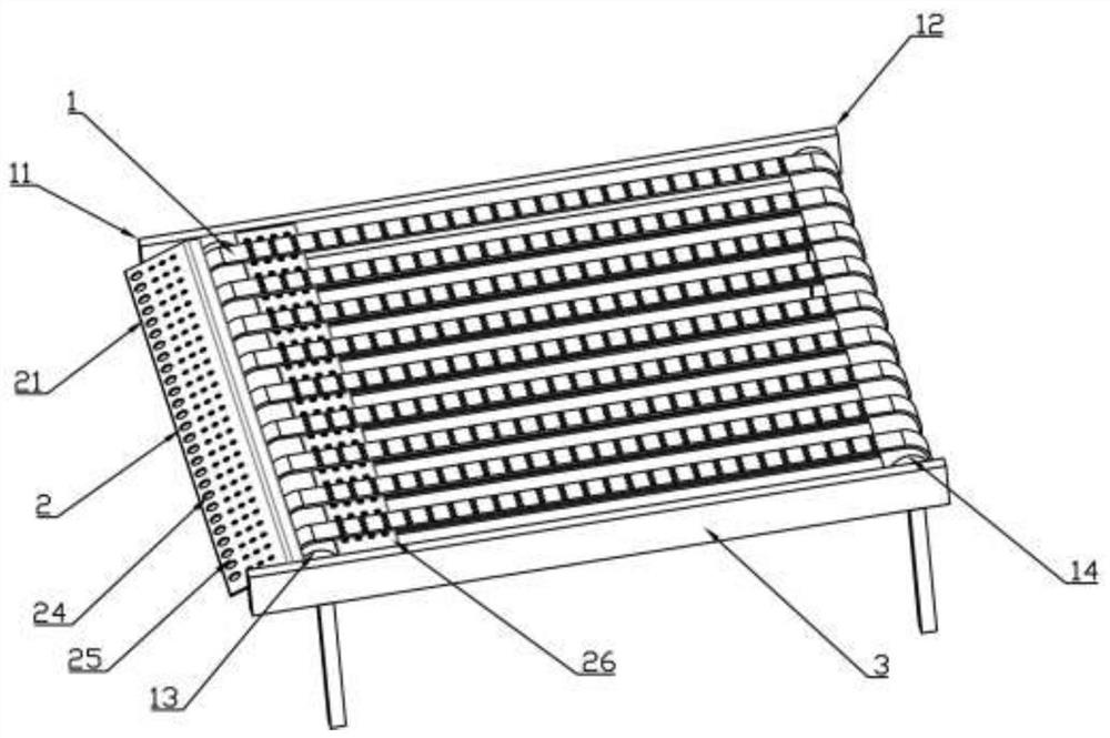
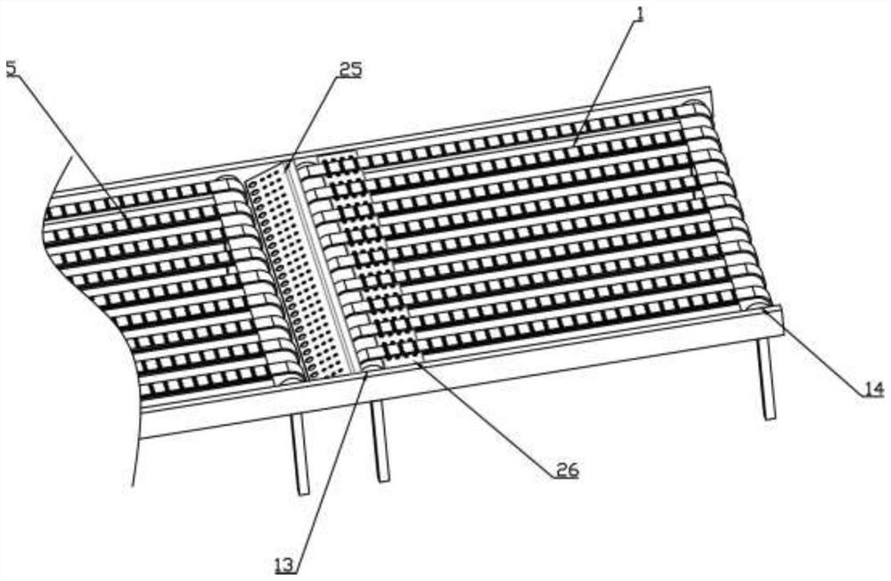
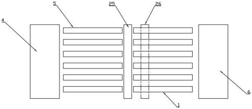
[0031] This embodiment discloses a deceleration mechanism for a paper slitter, including a slow delivery belt 1 , a vacuum suction device 2 and a bracket 3 . The vacuum suction device 2 is arranged below the slow-speed delivery belt 1 and absorbs the paper on the slow-speed delivery belt 1 . The bracket 3 supports the slow conveyor belt 1 and the vacuum suction device 2 .

[0032] The vacuum suction device 2 includes a vacuum plate 21 , a vacuum pump 22 and a conduit 23 connected to the vacuum pump 22 . An air suction hole 24 is provided on the upper surface of the vacuum plate 21 , and a downward suction force is formed at the air suction hole 24 after the vacuum plate 21 is sucked by the conduit 23 .

[0033] There are two vacuum panels 2 , including a first vacuum panel 25 and a second vacuum panel 26 . One end of the slow delivery belt 1 is a paper feed end 11, and one end is a paper discharge end 12. The two ends of the slow delivery belt 1 are provided with a paper fee...

Embodiment 2

[0038] This embodiment discloses a deceleration mechanism for a paper slitting machine.

[0039] Present implementation is provided with upper belt 7 above slow delivery belt 1 . The rotating speed of upper belt 7 is identical with slow delivery belt 1, and the direction of rotation is opposite to slow delivery belt 1. It can prevent the paper from flying up during conveying.

[0040] Other structures of this embodiment are the same as those of Embodiment 1.

Embodiment 3

[0042] This embodiment discloses a deceleration mechanism for a paper slitting machine.

[0043] In this embodiment, the suction hole 24 on the first vacuum plate 25 is larger at a lower position and smaller at a higher position. And the larger suction hole 24 that is positioned at the lower place is equipped with static elimination bar, can reach and make paper drop fast and eliminate the effect that its surface has static electricity.

[0044] Other structures of this embodiment are the same as those of Embodiment 1.


PUM


Abstract

The invention discloses a speed reducing mechanism of a paper splitting machine, which comprises a slow delivery belt, a vacuum suction device and a bracket, wherein the vacuum suction device is arranged below the slow delivery belt and adsorbs paper on the slow delivery belt, and the bracket supports the slow delivery belt and the vacuum suction device. Paper is adsorbed on the slow delivery belt through the vacuum suction device, the paper can be attached to the slow delivery belt under the condition that the coating face of the surface of the paper is not damaged, and the purpose of reducing the speed of the paper is achieved. When paper is decelerated, the paper is not damaged, light spots and pinch roller marks are prevented, a good printing effect is achieved, the qualified rate of products can be greatly increased, and economic losses are reduced.

Description

technical field [0001] The invention relates to the field of papermaking machinery, in particular to a deceleration mechanism for a paper slitting machine. Background technique [0002] The paper of the roll paper slitter is cut from the cross-cutting knife, passes through the fast delivery belt to the slow delivery belt, and then arrives at the stacking table for stacking. The paper must be decelerated from the express delivery belt to the docking table, otherwise the speed is too fast and the paper hits the docking table baffle, causing the paper to be damaged and become waste. Therefore, the paper must be decelerated by the slow delivery belt from the fast belt to the docking table. The deceleration requires that the speed of the slow delivery belt is slower than that of the fast delivery belt, but at this time, the paper will fly out of the deceleration mechanism without external force applied. [0003] Existing web slitting machine adopts the method of applying extern...

Claims


Application Information

Patent Timeline
Patent Type & Authority Applications(China)
IPC IPC(8): B26D7/32
CPCB26D7/32B26D2007/322
Inventor 卢宏旺
Owner 卢宏旺
Learn More