Automatic film winding device
A winding device and film technology, applied in packaging, winding strips, thin material processing, etc., can solve the problems of wasting time, labor, and resources, and achieve the effects of easy use, easy winding and wrapping, and easy flattening
- Summary
- Abstract
- Description
- Claims
- Application Information
AI Technical Summary
Problems solved by technology
Method used
Image

Examples
Embodiment Construction
[0023] The following will clearly and completely describe the technical solutions in the embodiments of the present invention with reference to the accompanying drawings in the embodiments of the present invention. Obviously, the described embodiments are only some, not all, embodiments of the present invention. Based on the embodiments of the present invention, all other embodiments obtained by persons of ordinary skill in the art without making creative efforts belong to the protection scope of the present invention.
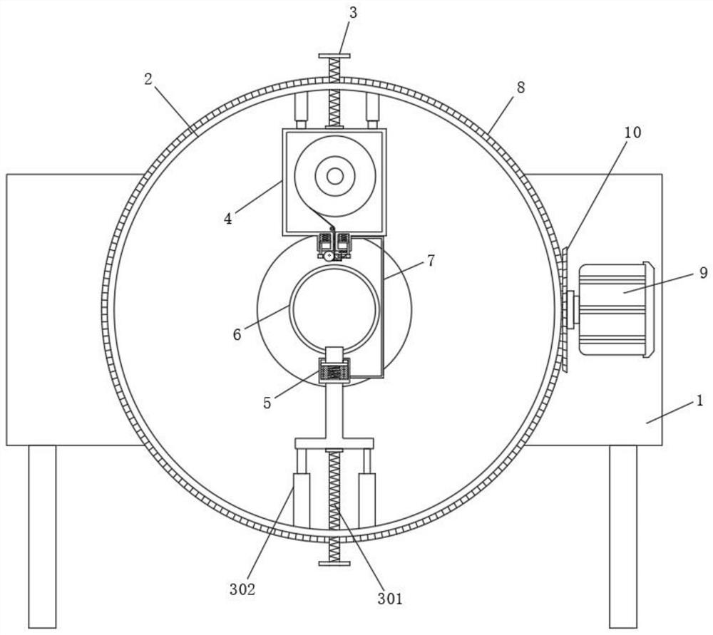
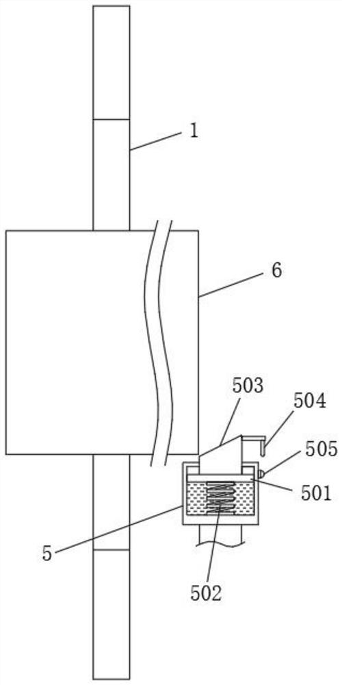
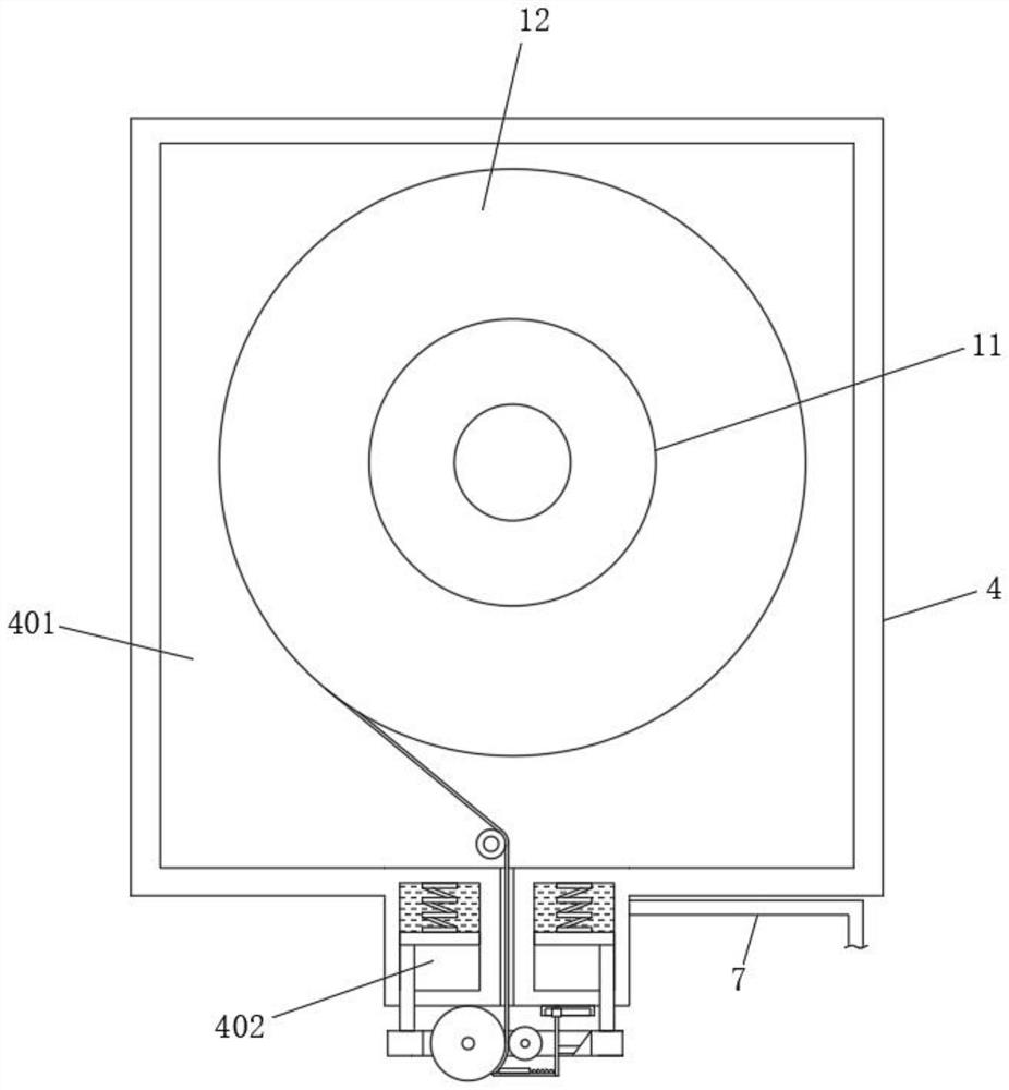
[0024] see Figure 1-5 , an embodiment provided by the present invention: an automatic film winding device, including a fixed plate 1, the front surface of the fixed plate 1 is rotatably connected to a sleeve 2, and the inside of the sleeve 2 is symmetrically provided with a device box 4 and a device box 5. In the middle of the front surface of the fixed plate 1, there is a steel coil 6 that penetrates to the rear surface of the fixed plate 1, and the steel co...
PUM
 Abstract
Description
Claims
Application Information