
Adhesive tape blanking system for adhesive tape production and using method thereof

A technology of adhesive tape and punching table, applied in the direction of final product manufacturing, thin material processing, climate sustainability, etc., can solve the problems of cumbersome operation steps, low punching efficiency, long punching time, etc., and speed up the punching process , improve the service life and save punching time

Active Publication Date: 2021-06-15
SHANGHAI RENHONG PRECISION MACHINERY
View PDF5 Cites 0 Cited by
  • Summary
  • Abstract
  • Description
  • Claims
  • Application Information

AI Technical Summary

Problems solved by technology

[0004] The Chinese invention with the patent number CN201911048037.0 in the prior art discloses a tape punching device for copper foil tape production, including a punching table fixedly connected to the upper end of the workbench, and a lifting cover is provided on the upper side of the punching table. There are multiple pairs of electric telescopic rods fixedly connected between the lifting cover and the workbench. A through hole is dug from top to bottom in the center of the lifting cover. A cylinder is connected to the center of the upper surface of the lifting cover. The power output end of the cylinder runs through the through hole. It is fixedly connected with a lifting block, and the lower end of the lifting cover plate is dug with a storage groove matching the lifting block, and the lower end of the lifting block is dug with a protective groove; this device can protect the cutter head from being easily corroded by the external environment, but there are still defects. In the process of using, when a group of cutter head assemblies are damaged, it is necessary to reversely store the damaged cutter head assemblies, and then reversely insert other previously idle cutter head assemblies to punch the tape. The operation steps are relatively simple. It is cumbersome, resulting in long punching time and low punching efficiency

Method used


Image

  • Adhesive tape blanking system for adhesive tape production and using method thereof
  • Adhesive tape blanking system for adhesive tape production and using method thereof
  • Adhesive tape blanking system for adhesive tape production and using method thereof

Examples


Embodiment 1

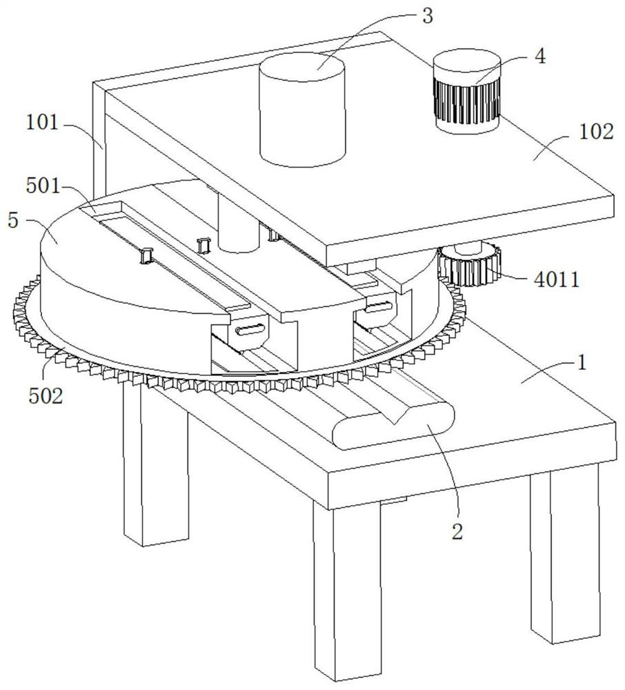
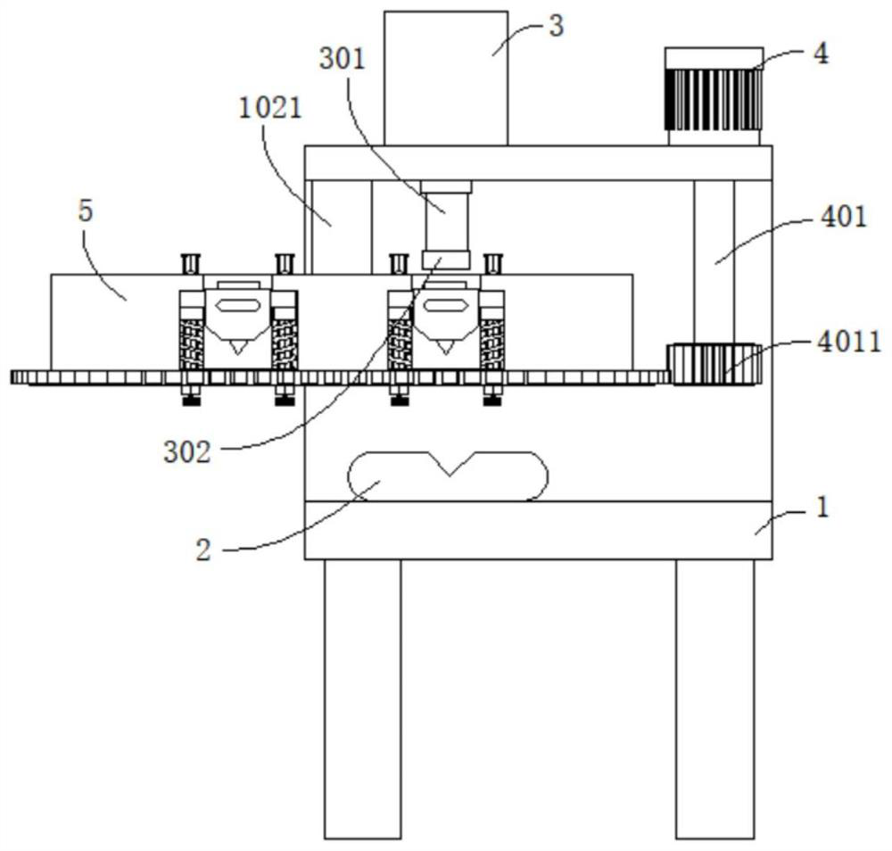
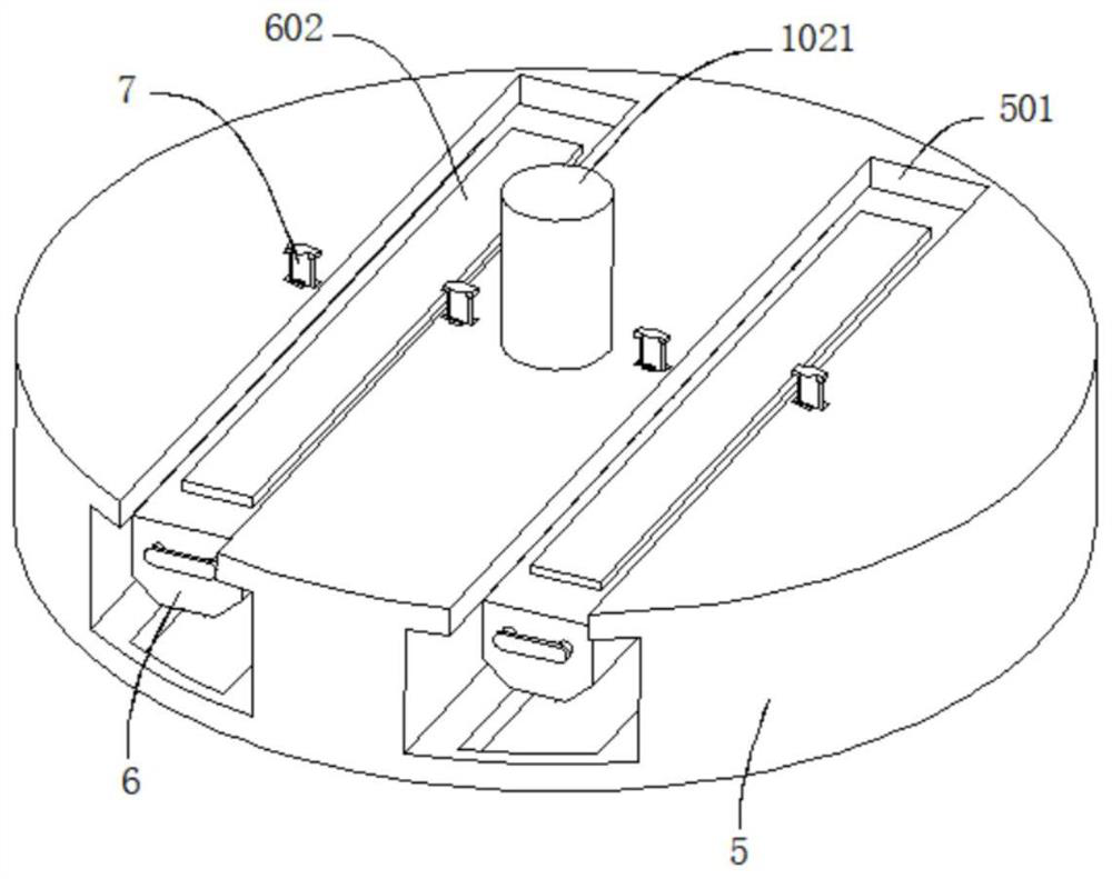
[0038] refer to Figure 1-5 , a tape punching system for adhesive tape production, comprising a workbench 1, a punching table 2 is connected to the top of the workbench 1, a connecting plate 101 is connected to the side wall of the workbench 1, and the end of the connecting plate 101 away from the workbench 1 is connected to There is a support plate 102, the top of the support plate 102 is connected with the cylinder 3 and the motor 4, the bottom of the support plate 102 is connected with the rotation column 1021 through the bearing rotation, and the end of the rotation column 1021 away from the support plate 102 is connected with the working block 5, the working block 5 Two installation grooves 501 are dug in the outer wall, and the cutter head assembly is movably connected in the installation groove 501. The output end of the cylinder 3 passes through the support plate 102 and is connected with the driving rod 301. The outer wall of the driving rod 301 is connected with a pre...

Embodiment 2

[0043] refer to Figure 3-10 , a tape blanking system for adhesive tape production, which is basically the same as that of Embodiment 1. Further, a positioning rod 7 is slidably connected in the installation groove 501, and the outer wall of the sliding block 603 and the moving plate 5012 is dug to match the positioning rod 7. The positioning rod 7 is slidably connected in the through hole, and the positioning rod 7 is placed in the inner ring of the first elastic element 5011 .

[0044] The top and the bottom of the positioning rod 7 are respectively connected with a top plate 701 and a bottom plate 702, the bottom plate 702 is offset against the bottom wall of the working block 5, and the outer walls of the working block 5, the moving plate 5012 and the sliding block 603 are all excavated with movable grooves matching the top plate 701 8.

[0045] Positioning rod 7 internal thread is connected with screw rod 11, and screw rod 11 outer wall is connected with knob 111, and on...

Embodiment 3

[0050] refer to Figure 1-10 , a tape blanking system for adhesive tape production, which is basically the same as that of Embodiment 2. Further, the outer wall of the positioning rod 7 is connected with a guide bar 9, and the outer wall of the working block 5 and the moving plate 5012 is dug with a guide bar 9. Guide groove 10; prevent positioning rod 7 from rotating with the rotation of screw rod 11, and improve the practicability of the device.

[0051] When in use, put the copper foil tape on the upper end surface of the punching table 2, then control the operation of the cylinder 3, so that the output end of the cylinder 3 drives the pressure plate 302 to move down through the drive rod 301, so that the pressure plate 302 exerts force on the cutter head assembly, and the knife The head mounting seat 6 is forced to drive the sliding block 603 to slide outside the positioning rod 7, the first elastic element 5011 is compressed, the cutter head mounting seat 6 drives the cut...


PUM


Abstract

The invention discloses an adhesive tape blanking system for adhesive tape production and a using method thereof, and belongs to the technical field of adhesive tape production. The adhesive tape blanking system for adhesive tape production comprises a workbench, the top of the workbench is connected with a blanking table, the side wall of the workbench is connected with a connecting plate, the end, away from the workbench, of the connecting plate is connected with a supporting plate, the top of the supporting plate is connected with an air cylinder and a motor, the bottom of the supporting plate is rotationally connected with a rotating column through a bearing, the end, away from the supporting plate, of the rotating column is connected with a working block, two mounting grooves are formed in the outer wall of the working block, tool bit assemblies are movably connected into the mounting grooves, the output end of the air cylinder penetrates through the supporting plate and is connected with a driving rod, the outer wall of the driving rod is connected with a pressing plate, the pressing plate movably abuts against the tool bit assemblies, and the output end of the motor is connected with a rotating shaft. The tool bit assemblies can be conveniently and rapidly replaced, the blanking time is saved, the blanking process is accelerated, and the working efficiency of adhesive tape production is improved.

Description

technical field [0001] The invention relates to the technical field of tape production, in particular to a tape punching system for tape production and a method for using the same. Background technique [0002] Adhesive tapes are widely used in daily life and have the functions of connecting, fixing, pasting and so on. Metal tape is mainly used for electromagnetic shielding, which is divided into two types: electrical signal shielding and magnetic signal shielding. The electrical signal shielding mainly relies on the excellent electrical conductivity of copper itself, while the magnetic shielding requires the conductive substance "nickel" on the rubber surface of the copper foil tape to It achieves the function of magnetic shielding, so it is widely used in mobile phones, notebook computers and other digital products. [0003] Punching is a stamping process that uses a die to separate part of the material or process part from another part of the material, process (process) ...

Claims


Application Information

Patent Timeline
Patent Type & Authority Applications(China)
IPC IPC(8): B65H35/00
CPCB65H35/008B65H35/0086B65H2701/173Y02P70/50
Inventor 陈冲
Owner SHANGHAI RENHONG PRECISION MACHINERY
Learn More