Heat dissipation device of electronic and electrical equipment

A heat dissipation device, electronic and electrical technology, which is applied to the structural parts of electrical equipment, electrical components, and decoration through conduction heat transfer, etc. Non-uniform material dispersion, uniform heat dissipation effect, and convenient operation

Pending Publication Date: 2021-06-15
何家祺
View PDF7 Cites 0 Cited by
  • Summary
  • Abstract
  • Description
  • Claims
  • Application Information

AI Technical Summary

Problems solved by technology

[0002] All kinds of electronic and electrical equipment currently on the market will generate heat or even generate high temperature under working conditions, and the heat dissipation method adopted by these equipment is often to use the principle of natural convection to drill holes in the casing, especially the back casing Or slits, when the electronic and electrical equipment is working, the heat will cause the internal temperature to be too high, and various harmful elements will be released after the heat is absorbed in the shell, which will cause adverse effects on people, and the heat dissipation effect of the existing electronic and electrical equipment is not good. Well, sometimes even electronic components can be destroyed due to overheating

Method used


Image

  • Heat dissipation device of electronic and electrical equipment
  • Heat dissipation device of electronic and electrical equipment

Examples


Embodiment 1

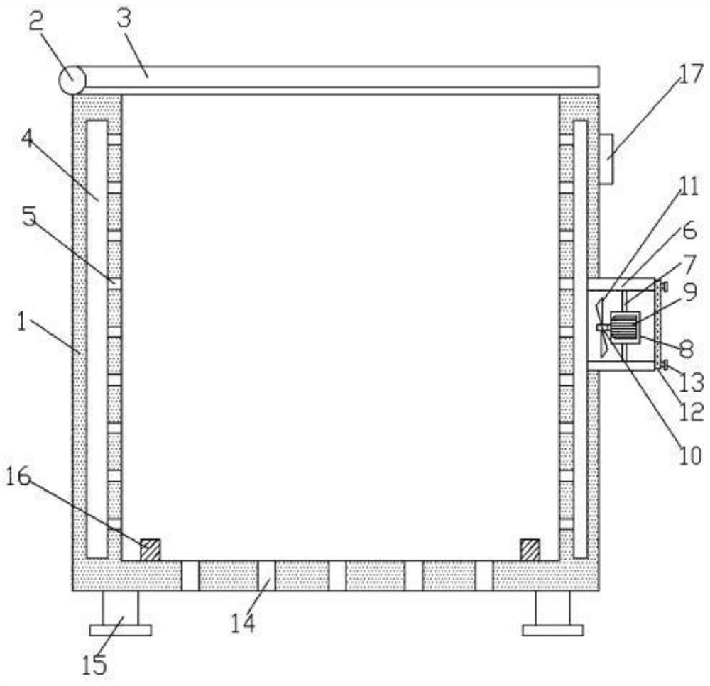
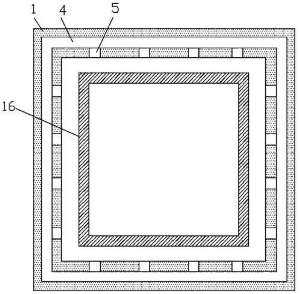
[0031] A heat dissipation device for electronic and electrical equipment, characterized in that it includes a heat dissipation cavity 1 and a cooling pipe 6; the heat dissipation cavity 1 has a cuboid structure, and the top surface of the heat dissipation cavity 1 is connected to the top cover 3 through a movable connection structure 2 to dissipate heat The chamber 1 has a double-layer structure, and a heat dissipation groove 4 is formed between the outer wall and the inner wall of the heat dissipation chamber 1. Several uniformly arranged ventilation holes 5 are arranged on the inner wall of the heat dissipation chamber 1. The bottom surface of the heat dissipation chamber 1 is provided with There are several evenly arranged cooling holes 14;

[0032] The heat dissipation cavity 1 is made of high thermal conductivity silica gel material, which is obtained by compounding organic silica gel and heat conduction material; the heat conduction material is composed of heat conduction...

Embodiment 2

[0049] A heat dissipation device for electronic and electrical equipment, characterized in that it includes a heat dissipation cavity 1 and a cooling pipe 6; the heat dissipation cavity 1 has a cuboid structure, and the top surface of the heat dissipation cavity 1 is connected to the top cover 3 through a movable connection structure 2 to dissipate heat The chamber 1 has a double-layer structure, and a heat dissipation groove 4 is formed between the outer wall and the inner wall of the heat dissipation chamber 1. Several uniformly arranged ventilation holes 5 are arranged on the inner wall of the heat dissipation chamber 1. The bottom surface of the heat dissipation chamber 1 is provided with There are several evenly arranged cooling holes 14;

[0050] The heat dissipation cavity 1 is made of high thermal conductivity silica gel material, which is obtained by compounding organic silica gel and heat conduction material; the heat conduction material is composed of heat conduction...

Embodiment 3

[0067] A heat dissipation device for electronic and electrical equipment, characterized in that it includes a heat dissipation cavity 1 and a cooling pipe 6; the heat dissipation cavity 1 has a cuboid structure, and the top surface of the heat dissipation cavity 1 is connected to the top cover 3 through a movable connection structure 2 to dissipate heat The chamber 1 has a double-layer structure, and a heat dissipation groove 4 is formed between the outer wall and the inner wall of the heat dissipation chamber 1. Several uniformly arranged ventilation holes 5 are arranged on the inner wall of the heat dissipation chamber 1. The bottom surface of the heat dissipation chamber 1 is provided with There are several evenly arranged cooling holes 14;

[0068] The heat dissipation cavity 1 is made of high thermal conductivity silica gel material, which is obtained by compounding organic silica gel and heat conduction material; the heat conduction material is composed of heat conduction...


PUM


Abstract

The invention relates to a heat dissipation device of electronic and electrical equipment. The heat dissipation device comprises a heat dissipation cavity and a cooling pipe; the heat dissipation cavity is of a cuboid structure, the top face of the heat dissipation cavity is connected with the top cover through a movable connecting structure, the heat dissipation cavity is of a double-layer structure, a heat dissipation groove is formed between the outer wall and the inner wall of the heat dissipation cavity, a plurality of evenly-arranged ventilation holes are formed in the inner wall of the heat dissipation cavity, and a plurality of uniformly arranged heat dissipation holes are formed in the bottom surface of the heat dissipation cavity; the heat dissipation cavity is made of a high-thermal-conductivity silica gel material, and the high-thermal-conductivity silica gel material is obtained by compounding organic silica gel and a thermal conductive material; and the thermal conductive material is composed of a thermal conductive filler, modified carbon nanotubes and a coupling agent. Blowing heat dissipation can be carried out on the periphery of the electronic and electrical equipment in the heat dissipation cavity at the same time, the heat dissipation effect is uniform, blown hot air is discharged through the heat dissipation holes in the bottom side of the heat dissipation cavity, the structure is simple, and operation is convenient.

Description

technical field [0001] The invention relates to the field of electronics and electrics, in particular to a heat dissipation device for electronic and electric equipment. Background technique [0002] All kinds of electronic and electrical equipment currently on the market will generate heat or even generate high temperature under working conditions, and the heat dissipation method adopted by these equipment is often to use the principle of natural convection to drill holes in its casing, especially the rear casing Or slits, when the electronic and electrical equipment is working, the heat will cause the internal temperature to be too high, and various harmful elements will be released after the heat is absorbed in the shell, which will cause adverse effects on people, and the heat dissipation effect of the existing electronic and electrical equipment is not good. Well, sometimes even electronic components can be destroyed due to overheating. Contents of the invention [0...

Claims


Application Information

Patent Timeline
Patent Type & Authority Applications(China)
IPC IPC(8): H05K7/20C08L83/04C08L83/07C08K3/38C08K3/28C08K3/22C08K3/34C08K9/02C08K9/04C08K3/04
CPCH05K7/20136H05K7/20509H05K7/20463C08K3/38C08K3/28C08K3/22C08K3/34C08K9/02C08K9/04C08K3/041C08L2203/20C08K2201/011C08K2003/385C08K2003/282C08K2003/2227C08L83/04
Inventor 何家祺
Owner 何家祺
Why Eureka
Try Eureka