
Turbine blade forging die and calibration method thereof

A steam turbine blade and mold technology, applied in the field of forging molds, can solve the problems of affecting the quality of forging products, the position of the upper mold and the lower mold do not correspond, economic losses, etc.

Active Publication Date: 2021-06-18
景德镇明兴航空锻压有限公司
View PDF5 Cites 0 Cited by
  • Summary
  • Abstract
  • Description
  • Claims
  • Application Information

AI Technical Summary

Problems solved by technology

Steam turbine blades are often produced by forging. Forging molds are needed in the forging production process. After a forging mold is used for a long time, due to the long-term violent collision between the molds, it is easy to appear that the positions of the upper mold and the lower mold do not correspond. At this time, if the forging die is not adjusted and calibrated, the quality of the forged product will be greatly affected. With traditional forging dies, it is difficult for the operator to understand the alignment of the upper die and the lower die in a timely and accurate manner, resulting in when the upper die is found When the mold and the lower mold are not aligned, some unqualified products have been produced, which will cause unnecessary economic losses

Method used


Image

  • Turbine blade forging die and calibration method thereof
  • Turbine blade forging die and calibration method thereof
  • Turbine blade forging die and calibration method thereof

Examples


Embodiment Construction

[0035]The following will clearly and completely describe the technical solutions in the embodiments of the present invention with reference to the accompanying drawings in the embodiments of the present invention. Obviously, the described embodiments are only some, not all, embodiments of the present invention. Based on the embodiments of the present invention, all other embodiments obtained by persons of ordinary skill in the art without making creative efforts belong to the protection scope of the present invention.

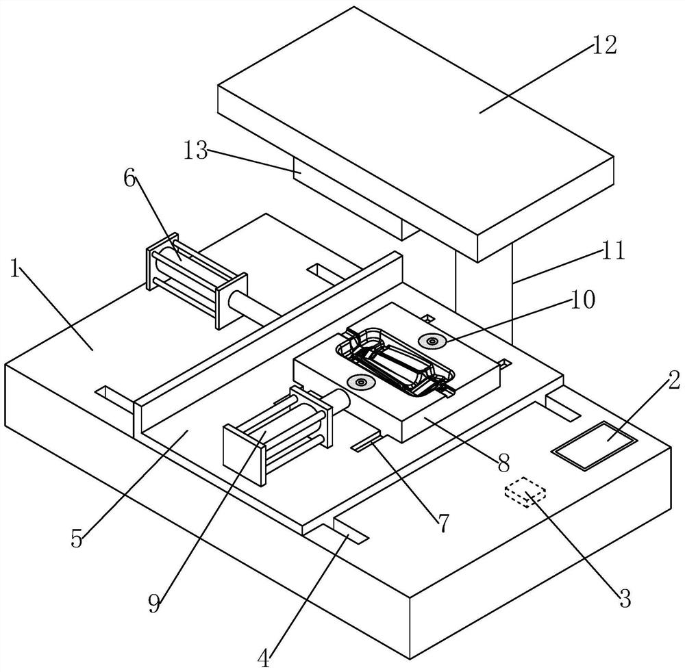
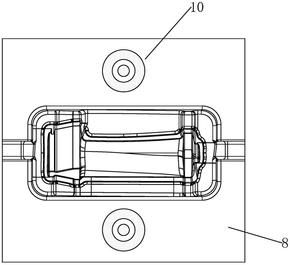
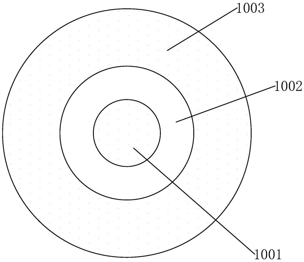
[0036] see Figure 1-5 ,in figure 1 It is an overall structural diagram of an embodiment of a steam turbine blade forging die of the present invention, figure 2 It is a top view of the lower die 8 of a steam turbine blade forging die embodiment of the present invention, image 3 It is a structural schematic diagram of the luminous cluster assembly 10 of an embodiment of a steam turbine blade forging die of the present invention, Figure 4 It is a bottom vie...


PUM


Abstract

The invention discloses a turbine blade forging die and a calibration method thereof, and belongs to the technical field of forging dies. According to the technical scheme, the turbine blade forging die comprises a workbench, a lower die body arranged on the workbench, a top plate, an upper die body arranged on the top plate and a die power mechanism used for providing die press-fitting power, a single-chip microcomputer processor is arranged in the workbench in an embedded mode, at least two light-emitting cluster assemblies are arranged on the side, facing the upper die body, of the lower die body, each light-emitting cluster assembly comprises a first light-emitting part and a second light-emitting part which can emit light beams of different colors, each second light-emitting part is in a circular ring shape, each first light-emitting part is in a round cake shape and is located at the circle center of the inner side of the corresponding second light-emitting part, and at least two light receiving assemblies are arranged on the side, facing the lower die body, of the upper die body. According to the turbine blade forging die, an operator can timely and accurately know the alignment condition of the upper die body and the lower die body. According to the calibration method for the turbine blade forging die, automatic calibration of the lower die body and the upper die body is realized, and operation is easy and accurate.

Description

technical field [0001] The invention relates to the technical field of forging dies, in particular to a steam turbine blade forging die and a calibration method thereof. Background technique [0002] The steam turbine blade is the key part of the steam turbine, and it is also one of the most delicate and important parts. Under extremely harsh conditions, it withstands the combined effects of high temperature, high pressure, huge centrifugal force, steam force, steam excitation force, corrosion and vibration, and water droplet erosion in the wet steam area. Its aerodynamic performance, machining geometry, surface roughness, installation clearance, operating conditions, scaling and other factors all affect the efficiency and output of the steam turbine; its structural design, vibration intensity and operation mode play an important role in the safety and reliability of the unit. decisive influence. Steam turbine blades are often produced by forging. Forging molds are needed ...

Claims


Application Information

Patent Timeline
IPC IPC(8): B21J13/02B21J13/00B21K3/04
CPCB21J13/02B21J13/00B21K3/04
Inventor 余亮亮毕民主计亮亮万玉玲王杨江毕江华毕文海
Owner 景德镇明兴航空锻压有限公司
Learn More