
Vertical drilling device for roof of steel skeleton composite building

A vertical drilling and building technology, applied in drilling/drilling equipment, portable drilling rigs, workbenches, etc., can solve problems such as cumbersome drilling process, inability to ensure drilling direction, and inability to effectively achieve drilling positioning. , to achieve the effect of increasing friction, high punching efficiency and ensuring accuracy

Active Publication Date: 2021-06-18
浙江宝盛建设集团有限公司
View PDF8 Cites 1 Cited by
  • Summary
  • Abstract
  • Description
  • Claims
  • Application Information

AI Technical Summary

Problems solved by technology

[0003] However, a vertical drilling device for the roof of a steel frame composite building currently on the market has the following problems during use: a. Due to installation requirements, the position of the roof on the top of the steel frame is different, some are arranged parallel to the horizontal plane, and some are inclined It is arranged on the horizontal plane, and the traditional vertical drilling device for the roof of the steel frame composite building cannot effectively realize the positioning of the drilling when drilling the roof at the above position, that is, it cannot ensure that the drilling direction is perpendicular to the horizontal plane, resulting in Subsequent positioning and locking of the top plate cannot be performed normally; b. When drilling manually, since the drilling area on the top is located directly above the operator, in order to avoid the waste generated by the drilling from falling on the operator and causing harm, Especially for the eyes, it is necessary to arrange waste collection bags and other protective equipment at the drilling position before each drilling, but this type of protective equipment cannot be recycled, causing the operator to arrange it every time a hole is drilled, resulting in the entire The drilling process is cumbersome

Method used


Image

  • Vertical drilling device for roof of steel skeleton composite building
  • Vertical drilling device for roof of steel skeleton composite building
  • Vertical drilling device for roof of steel skeleton composite building

Examples


Embodiment Construction

[0026] The embodiments of the present invention will be described in detail below with reference to the accompanying drawings, but the present invention can be implemented in many different ways defined and covered by the claims.

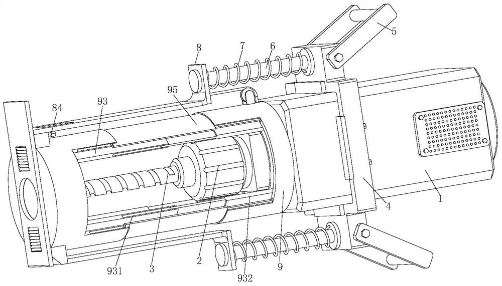
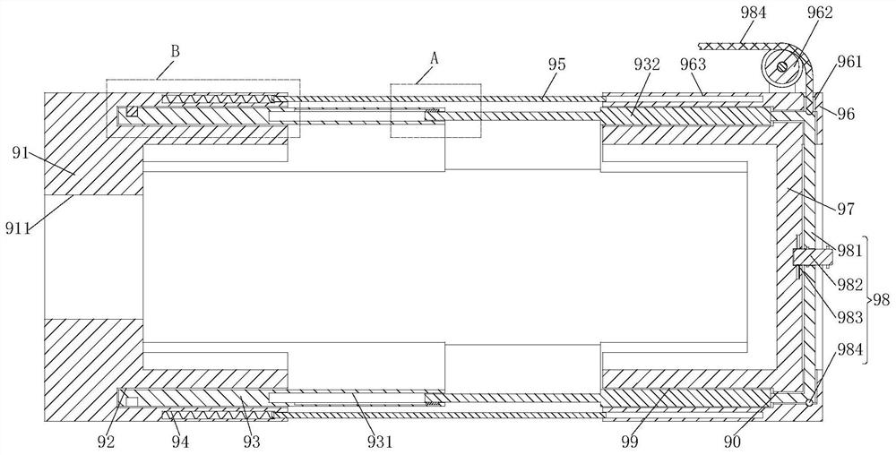
[0027] Such as Figure 1 to Figure 6 As shown, a vertical drilling device for the roof of a steel frame composite building includes a drive motor 1, a fixed end 2, a drill bit 3, a fixed frame 4, a handle 5, a positioning support rod 6, a support spring 7, a vertical positioning mechanism 8 and The sealing mechanism 9, the output shaft end of the drive motor 1 is equipped with a fixed end 2, and one end of the fixed end 2 is equipped with a drill bit 3, and the shell of the drive motor 1 is fixed with a fixed frame 4 by bolts, and the fixed frame 4 Both ends are symmetrically equipped with handles 5, and the upper end face of the fixed frame 4 is symmetrically welded with a positioning support rod 6, and one end of the vertical positioning mechanism...


PUM


Abstract

The invention relates to a vertical drilling device for a roof of a steel skeleton composite building. The device comprises a driving motor, a fixing end, a drill bit, a fixing frame, handles, positioning supporting rods, supporting springs, vertical positioning mechanisms and sealing mechanisms, wherein the output shaft end of the driving motor is provided with the fixing end, one end of the fixing end is provided with the drill bit, the fixing frame is fixedly installed at a shell of the driving motor through bolts, the handles are symmetrically installed at the two ends of the fixing frame, the positioning supporting rods are symmetrically welded to the upper end face of the fixing frame, one ends of the vertical positioning mechanisms are connected with the positioning supporting rods, the outer walls of the two positioning supporting rods are both sleeved with the supporting springs, the sealing mechanisms are arranged on the inner walls of the vertical positioning mechanisms, and a shaft hole is formed in the center of one end face of the shell of the driving motor. According to the device, the vertical drilling requirements of roofs with different angles can be met, the sealing mechanisms are arranged, waste chips generated during drilling are effectively prevented from falling onto operators, and the practicability is higher.

Description

technical field [0001] The invention relates to the technical field of drilling equipment, in particular to a vertical drilling device for the roof of a steel skeleton composite building. Background technique [0002] The steel frame composite building is a kind of building combined with steel frame, cold-drawn steel wire mesh and roof. A complete steel grid is conducive to confining concrete and improving the integrity of concrete components. Among them, the reinforcement mesh generally refers to the combination of planar reinforcement, such as the vertical and horizontal reinforcement in the floor; the reinforcement skeleton generally refers to the combination of three-dimensional reinforcement, such as the reinforcement in the beam and column. The steel frame is pre-lashed, and the top is laid on top of the steel frame. In the actual construction process, it is necessary to manually drill holes on the top through drilling equipment, and then install the fixing mechanism...

Claims


Application Information

Patent Timeline
Patent Type & Authority Applications(China)
IPC IPC(8): B23B45/02B23B45/14
CPCB25H1/0021B23B45/02
Inventor 周杨军邵国夫孟立锋周飞良邵国华
Owner 浙江宝盛建设集团有限公司
Learn More