Emergency stop type engineering machinery for transportation
A construction machinery, emergency stop technology, used in conveyors, conveyor objects, transportation and packaging, etc., can solve the problems of conveyor belt waste, hidden safety hazards, and difficult to control additions.
- Summary
- Abstract
- Description
- Claims
- Application Information
AI Technical Summary
Problems solved by technology
Method used
Image

Examples
specific Embodiment approach 1
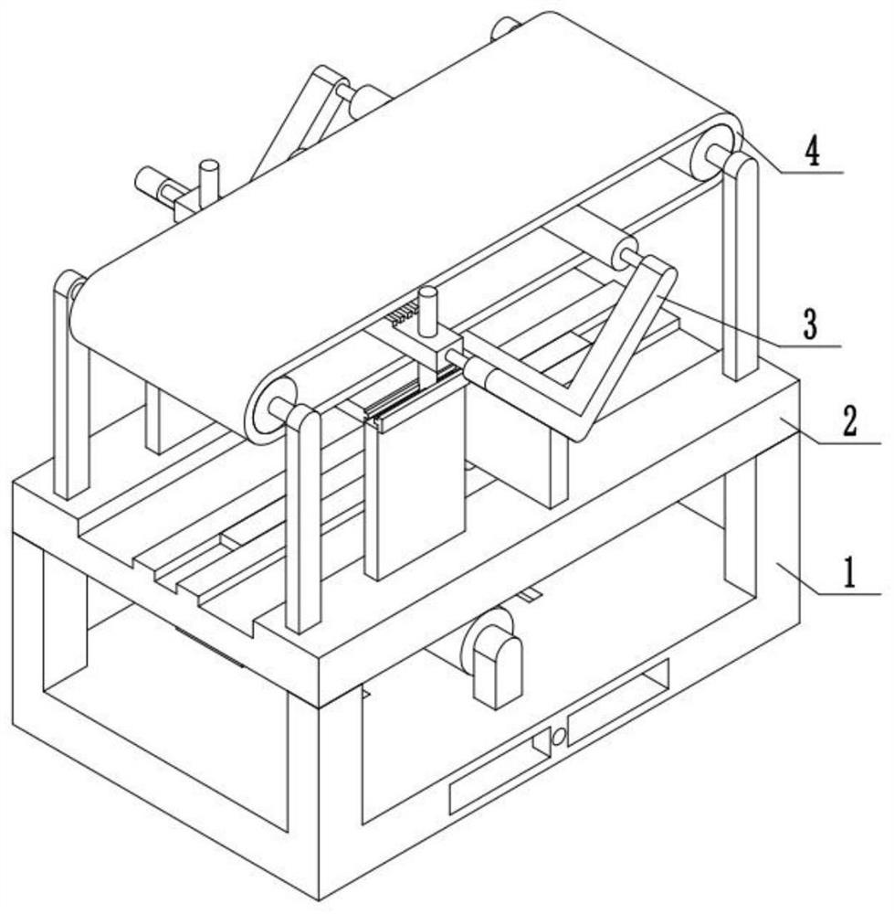
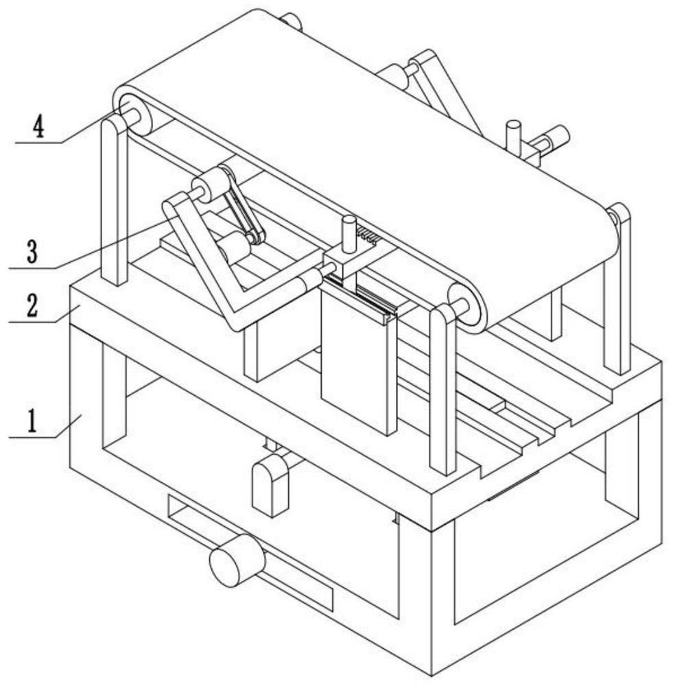
[0033] Bonded below figure 1 , 2 According to the present embodiment, an emergency stop transport is a construction machine, including the power driver 1, the connection medium plate 2, the feed emergency stop control device 3, and the transport device 4, the power supply device 1 fixed mounting There is a connection medium plate 2, and the feed emergency stop control device 3 is attached to the middle plate 2, and the feed emergency stop control device 3 is mounted on the power supply device 1, and the transport device 4 is fixed to the upper side of the connection medium 2.
specific Embodiment approach 2
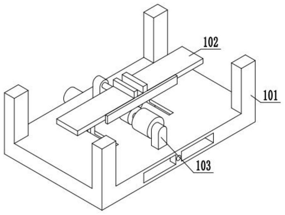
[0035] Bonded below image 3 , 45, 6, 7, 8, 9, 10, 11,,,,,,,,,,,,,,,,,,,,,,,,,,,,,,,,,,,,,,,,,,,,,,,,,,,,,,,,,,,,,,,,,,,,,,,,,,,,,,,,,,,,,,,,,,,,,,,,,,,,,,. The mechanism 103 is fixedly mounted on the mounting base 101, and the mounting base 101 is mounted and mounted is attached to the power mechanism 102 and the power mechanism 103 is connected;
[0036] The drive mechanism 102 includes a positive inverting motor 104, a drive screw 105, a push plate 107, a push wheel 108, a rib 110, a top moving plate 111, a roast wheel 112, a spring 113 The spring connecting plate 114, the output of the positive inversion motor 104 is mounted with a drive screw 105, and the drive screw 105 is mounted by the thread, and the drum 106 is slidably mounted on the mounting base 101, and the concave grooves 106 The push plate 107 is attached to the push plate 107, and the push wheel 108 is attached to the push plate 107, and the push wheel 108 is in contact with the rod 110, and the rod 110 is slidably...
specific Embodiment approach 3
[0039] Bonded below Figure 12 , 13 In the present embodiment, the present embodiment further illustrates the embodiment, and the feed emergency stop control device 3 includes a casing 301, a connecting post 302, a rack 303, a gear 304, a gear connecting plate 305, a V type Shelf 306, the power motor B307, the drive belt 308, the driven shoulder 309, the brake tooth plate 310, the guide rod 311, the guide rod coupling frame 312, the casing 301 is mounted on the upper plate 109, and the upper portion of the casing 301 is fixedly mounted The connecting post 302 is fixed to the upper side of the connecting post 302, and the drive rack 303 is mounted, and the drive rack 303 is slidably mounted on the connection medium 2, and the rack 303 is engaged with the drive gear 304, and the gear 304 is fixedly mounted in the gear. On the connecting plate 305, the upper portion of the gear connection plate 305 is fixedly mounted, and the V-shaped frame 306 is fixedly mounted, and the power motor ...
PUM
 Abstract
Description
Claims
Application Information
 - R&D Engineer
- R&D Manager
- IP Professional
- Industry Leading Data Capabilities
- Powerful AI technology
- Patent DNA Extraction
Browse by: Latest US Patents, China's latest patents, Technical Efficacy Thesaurus, Application Domain, Technology Topic.
© 2024 PatSnap. All rights reserved.Legal|Privacy policy|Modern Slavery Act Transparency Statement|Sitemap