Assembly type self-resetting buckling restrained brace

A buckling restraint and self-resetting technology, which is applied in protective buildings/shelters, building components, earthquake resistance, etc., can solve the problems of high cost, large internal force and damage of connecting nodes and adjacent components, and achieve structural interlayer deformation Uniformity, improve collapse resistance, and prevent concentrated deformation

Inactive Publication Date: 2021-06-18
TONGJI UNIV
View PDF3 Cites 11 Cited by
  • Summary
  • Abstract
  • Description
  • Claims
  • Application Information

AI Technical Summary

Problems solved by technology

[0003] (1) As a reset material, steel strands have insufficient elastic deformation capacity, and it is difficult to anchor composite fiber bars. Shape memory alloy (SMA) has superior deformation capacity, but its cost is high, and its mechanical properties are greatly affected by temperature. Butterfly Shaped springs can meet different bearing capacity and deformation requirements through reasonable combination, but self-resetting buckling restraint supports based on disc springs often require a lot of welding or assembly work;
[0004] (2) The energy-dissipating inner cores of existing self-resetting buckling-restrained braces are often connected by welding, and it is difficult to replace damaged parts after the earthquake;
[0005] (3) If the stiffness of the brace after yielding is too small, the interstory deformation concentration effect of the structure under strong earthquakes cannot be effectively suppressed, and if the stiffness after yielding is too large, the internal force of the connecting nodes and adjacent components of the brace will be too large and damaged

Method used


Image

  • Assembly type self-resetting buckling restrained brace
  • Assembly type self-resetting buckling restrained brace
  • Assembly type self-resetting buckling restrained brace

Examples


Embodiment Construction

[0035] The technical solutions of the present invention will be further described below with reference to the drawings and specific implementation methods.

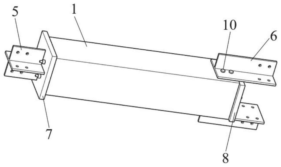
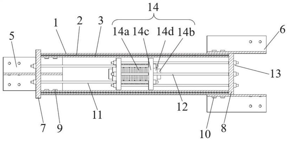
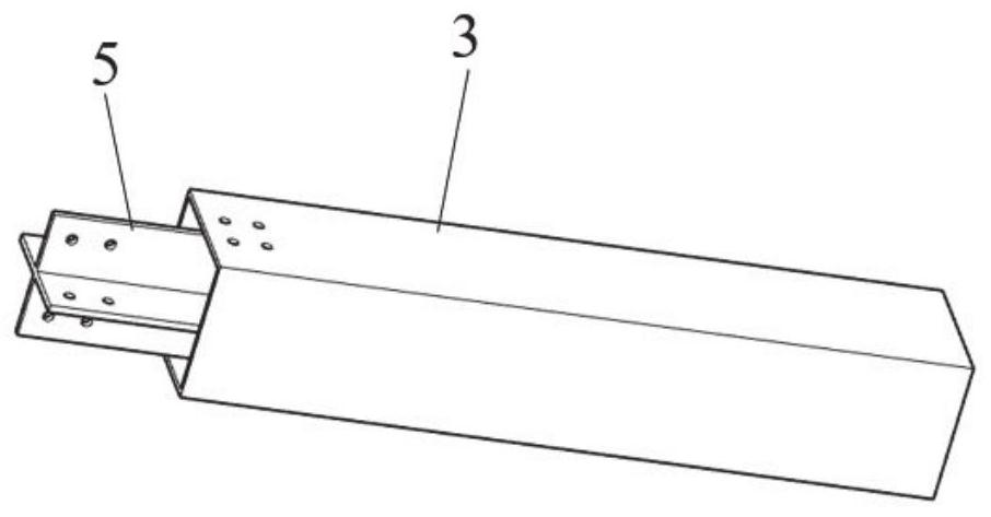
[0036] An assembled self-resetting buckling-restrained brace, such as Figure 1-9 As shown, the assembly includes an outer tube 1, an energy-dissipating inner core 2, an inner tube 3, a left connector 5, a right connector 6, a left end plate 7, a right end plate 8, the first group of prestressed steel strands 11, the first Two groups of prestressed steel strands 12 and disc spring reset device 14.

[0037] The left connecting piece 5 is connected to the inner pipe 3 by welding, and the right connecting piece 6 is connected to the outer pipe 1 by welding. The energy dissipation inner core 2 is located between the inner tube 3 and the outer tube 1 , and its left end is connected with the inner tube 3 by a self-tapping screw 9 , and its right end is connected with the outer tube 1 by a self-tapping screw 10 . The first gro...


PUM


Abstract

The invention relates to an assembly type self-resetting buckling restrained brace. The assembly type self-resetting buckling restrained brace mainly comprises an energy-consuming inner core, an inner pipe, an outer pipe, a connecting piece, an end plate, two groups of prestressed steel strands and a disc spring resetting device. The inner pipe and the outer pipe are force transmission parts of a resetting system and are also restraining parts of the energy-consuming inner core, so that the energy-consuming inner core does not need to be independently provided with the restraining parts, and the material consumption is reduced; the energy-consuming inner core is connected with the inner pipe and the outer pipe through self-tapping screws, so that the brace is convenient to assemble and replace after an earthquake; the resetting system is formed by connecting the two groups of prestressed steel strands and the disc spring resetting device in series, so that the deformation capability of the brace is greatly enhanced; after a disc spring combination in the resetting system is pressed under the action of external force, the supporting rigidity is increased, so that deformation concentration among structural layers can be prevented, the deformation among the structural layers is more uniform, and the collapse resistance of the structure under the action of a rare earthquake or even a very rare earthquake is effectively improved.

Description

technical field [0001] The invention relates to the technical field of energy dissipation and shock absorption in civil engineering. Background technique [0002] Buckling-restrained bracing (BRB) is more and more used in the field of construction engineering due to its full hysteretic curve, strong energy dissipation capacity, and similar tension and compression performance. Scholars at home and abroad have also conducted extensive research on BRB and BRB frame structures . Although BRB makes up for the shortcomings of traditional centrally braced frames that are prone to compressive buckling under strong earthquakes, related studies have shown that due to the low stiffness of BRB after yielding, the structure is prone to interstory deformation concentration under strong earthquakes, and there are obvious seismic shocks. Post-residual deformation. Self-resetting energy-dissipating supports have become a research hotspot in recent years because they have both energy-dissip...

Claims


Application Information

Patent Timeline
Patent Type & Authority Applications(China)
IPC IPC(8): E04B1/98E04H9/02
CPCE04B1/98E04H9/021
Inventor 张超众郭小农王丽
Owner TONGJI UNIV
Why Eureka
Try Eureka