Concrete filling and pouring method for connecting upper column section and lower column section of prefabricated steel reinforced concrete column

A technology of concrete and section steel, applied in the direction of columns, pier columns, pillars, etc., can solve problems such as construction difficulties, and achieve the effects of solving construction difficulties, reducing construction difficulty, and high precision

Inactive Publication Date: 2021-06-18
ZHONGCHUAN NO 9 DESIGN & RES INST
View PDF8 Cites 0 Cited by
  • Summary
  • Abstract
  • Description
  • Claims
  • Application Information

AI Technical Summary

Problems solved by technology

[0005] The purpose of the present invention is to provide a method of pouring concrete for connecting the upper and lower column sections of prefabricated steel concrete columns in view of the deficiencies in the prior art. PC structure technology is used to design the joints of prefabricated steel-concrete columns, and the prefabricated steel concrete The column and the steel beam are used as a prefabricated unit, and the connection nodes of the upper and lower columns are moved to the middle of the column, and the steel bar and the section steel in the upper and lower prefabricated reinforced concrete columns are connected by using the filament sleeve and the steel structure ear plate connection process, and then The pea-stone type grouting material is used to pour the connection space between the upper and lower column sections into a prefabricated integral structural column, which better solves the difficult problem of on-site construction of the traditional steel-concrete column structure. The structure is simple, the force is safe, and the construction is easy. Convenient, the steel concrete column fully realizes factory production, high production efficiency, more controllable quality, and can combine the characteristics of PC structure to form a new structural system with better force and construction performance, especially suitable for steel concrete column-steel beam frame structure

Method used


Image

  • Concrete filling and pouring method for connecting upper column section and lower column section of prefabricated steel reinforced concrete column
  • Concrete filling and pouring method for connecting upper column section and lower column section of prefabricated steel reinforced concrete column
  • Concrete filling and pouring method for connecting upper column section and lower column section of prefabricated steel reinforced concrete column

Examples


Embodiment 1

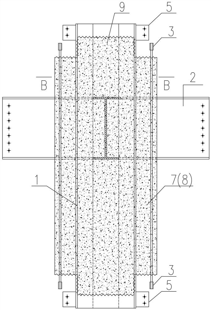
[0015] See attached figure 1 , the prefabricated steel-concrete column unit structure of the present invention includes the upper prefabricated steel concrete column 7 (or the lower prefabricated steel concrete column 8 of the steel bar 10 and the steel skeleton 1, and the two ends of the upper prefabricated steel concrete column 7 are provided with the steel skeleton 1 The enveloping concrete boss 9, the steel bar 10 is provided with a threaded sleeve 3, and the upper part of the upper prefabricated steel concrete column 7 (or the lower prefabricated steel concrete column 8) is provided with a steel frame 1 for welding. The floor steel beam 2; the floor steel beam 2 is symmetrically arranged on both sides of the upper prefabricated steel concrete column 7 (or the lower prefabricated steel concrete column 8); Welded lugs5.

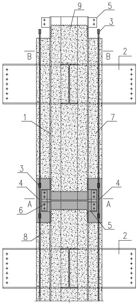
[0016] See attached Figure 2~Figure 3 , the upper prefabricated steel concrete column 7 is set on the lower prefabricated steel concrete column 8, and ...


PUM


Abstract

The invention discloses a concrete filling and pouring method for connecting an upper column section and a lower column section of a prefabricated steel reinforced concrete column. The method is characterized in that filament sleeves and lug plates are used for connecting steel bars and a profile steel framework in upper and lower prefabricated steel reinforced concrete columns into a whole; a pisolite type grouting material is used for pouring a connecting area of the upper and lower columns to form an assembly type integral structure column; the filament sleeves are arranged on the reinforcing steel bars at the two ends of the upper and lower prefabricated steel reinforced concrete columns and are in screwed connection with the reinforcing steel bars; and floor steel beams welded with the profile steel framework are arranged at the upper parts of the upper and lower prefabricated profile steel concrete columns. Compared with the prior art, the concrete filling and pouring method for connecting the upper column section and the lower column section of the prefabricated steel reinforced concrete column has the advantages that joint connection is moved to the middle of the column, beam-column joints with complex structures are avoided, construction quality and stress safety are guaranteed, factory production of the prefabricated steel reinforced concrete column is achieved, production efficiency is high, quality is more controllable, and the problem that an existing steel reinforced concrete column structure is difficult to construct on site is well solved.

Description

technical field [0001] The invention relates to the technical field of prefabricated structure design, in particular to a concrete filling method suitable for connecting upper and lower column sections of prefabricated steel concrete columns in factories. Background technique [0002] In recent years, the construction scale of high-rise buildings in my country ranks among the top in the world. While the building height continues to increase, the building shape is also becoming more and more complex, and most of them are developing in the direction of large spans and heavy loads, so that the structural columns bear more and more loads. In order to reduce the cross-sectional area of ​​traditional reinforced concrete column members and expand the actual use area of ​​the building, the steel-concrete column structure has gradually become a load-bearing and lateral force-resistant structural member commonly used in high-rise and super high-rise buildings. The section steel-concre...

Claims


Application Information

Patent Timeline
Patent Type & Authority Applications(China)
IPC IPC(8): E04C3/34E04C3/32E04B1/58
CPCE04C3/34E04C3/32E04B1/5831
Inventor 朱伟华连军曹吴臻武奕文王鑫
Owner ZHONGCHUAN NO 9 DESIGN & RES INST
Why Eureka
Try Eureka