Automobile oil-gas separation valve

A separation valve, oil and gas technology, applied in the direction of engine components, machines/engines, mechanical equipment, etc., can solve the problems of high crankcase pressure, air leakage and oil leakage at joints, affecting engine performance, etc., to prolong transmission time and improve filtration. effect, the effect of improving usability

Inactive Publication Date: 2021-06-18
新昌县寅创汽车配件有限公司
View PDF6 Cites 0 Cited by
  • Summary
  • Abstract
  • Description
  • Claims
  • Application Information

AI Technical Summary

Problems solved by technology

[0004] In the existing oil-gas separation system, the spool of the one-way valve generally does not move smoothly, so that the oil and gas cannot flow into the intake passage smoothly, resulting in the backflow of fresh mixed gas in the intake pipe when the engine is under small load or the engine is not working. Poor movement of the valve core will also affect the ventilation of the crankcase. In the long run, the engine will work for a long time, which will lead to excessive pressure in the crankcase, which will easily cause air leakage and oil leakage at each joint, and the engine power will also increase accordingly. affect engine performance

Method used


Image

  • Automobile oil-gas separation valve
  • Automobile oil-gas separation valve
  • Automobile oil-gas separation valve

Examples


Embodiment Construction

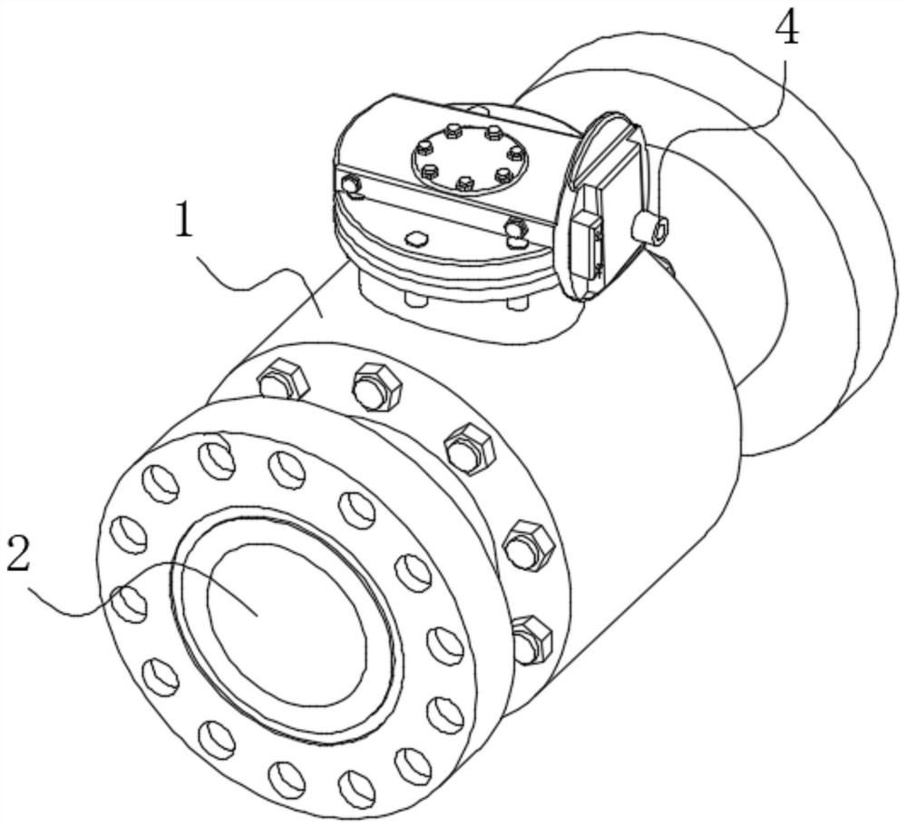
[0021] use Figure 1-Figure 5 An automotive oil-air separation valve according to one embodiment of the present invention will be described below.

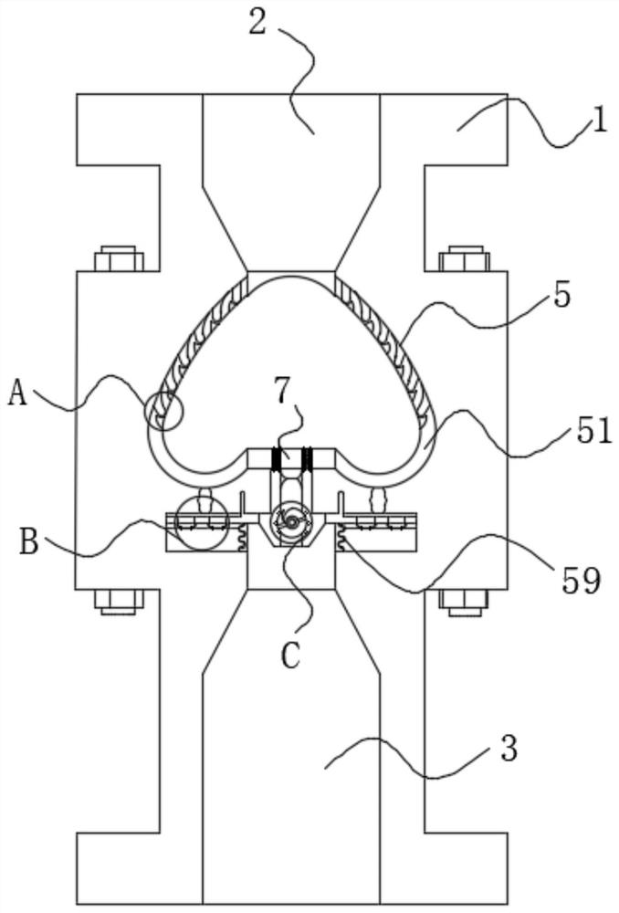
[0022] Such as Figure 1-Figure 5As shown, a kind of oil-gas separation valve for automobiles according to the present invention comprises valve body 1, air inlet hole 2, air outlet hole 3, oil-gas pipe 4 and separation mechanism 5; An air hole 2, an air outlet hole 3 is provided in the lower end wall of the valve body 1, and an oil and gas pipe 4 is fixedly connected to the outer wall of the middle part of the valve body 1; the air inlet hole 2 communicates with the air outlet hole 3 through a separation mechanism 5; the separation The mechanism 5 communicates with the oil and gas pipe 4 .

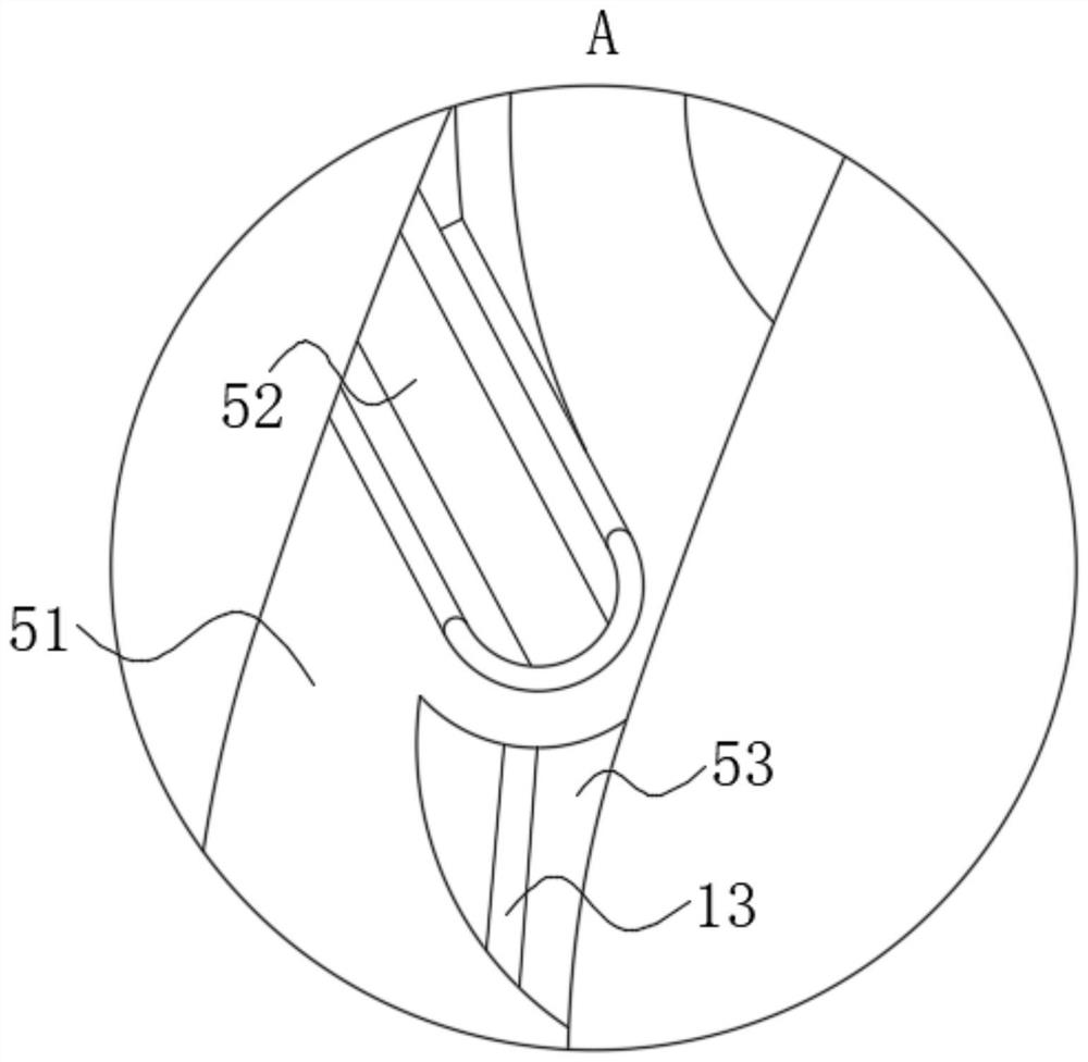
[0023] Described separation mechanism 5 comprises dredge hole 51, filter plate 52, deflector 53, communication groove 54, collection tank 55, extruding plate 56, liquid flow groove 57, sponge ring 58 and bellows 59; The hole 51 is located ...


PUM


Abstract

The invention belongs to the technical field of automobile accessories, and particularly relates to an automobile oil-gas separation valve. The automobile oil-gas separation valve comprises a valve body, a gas inlet hole, a gas outlet hole, an oil-gas pipe and a separation mechanism. The gas inlet hole is formed in the upper end wall of the valve body, the gas outlet hole is formed in the lower end wall of the valve body, and the oil-gas pipe is fixedly connected to the outer wall of the middle of the valve body; the gas inlet hole communicates with the gas outlet hole through the separation mechanism; the separation mechanism communicates with the oil-gas pipe; and when an extrusion plate is reset, a filter screen plate is gradually reset, so that a collecting groove communicates with a flow dredging hole, at the moment, a sponge ring generates a suction force on oil liquid existing in the communicating groove in a negative pressure state, then it is ensured that the oil liquid in the collecting groove can be completely adsorbed every time the extrusion plate works, and the situation that oil exists in exhausted gas due to the fact that the flow dredging hole is blocked due to excessive oil is avoided.

Description

technical field [0001] The invention belongs to the technical field of auto parts, in particular to an oil-gas separation valve for automobiles. Background technique [0002] With the advancement of society and the rapid development of the automobile industry, people's living standards continue to improve, and automobiles have become one of the important means of transportation for people to travel. The engine is the heart of the car. The part used to install the crankshaft at the lower part of the engine block of the car is called the crankcase. The crankcase is divided into an upper crankcase and a lower crankcase. Used to store lubricating oil and seal the upper crankcase. [0003] When the engine is working, a part of the combustible mixture and exhaust gas will always escape into the crankcase through the piston ring, and the gasoline vapor condensed in the crankcase will make the engine oil thinner and the performance will deteriorate, and the exhaust gas will contain...

Claims


Application Information

Patent Timeline
Patent Type & Authority Applications(China)
IPC IPC(8): F01M13/04
CPCF01M13/04F01M2013/0438
Inventor 钱国锋
Owner 新昌县寅创汽车配件有限公司
Why Eureka
Try Eureka