
Three-way catalyst detecting and cleaning device

A three-way catalytic converter and cleaning device technology, applied in the direction of muffler device, exhaust device, electric control of exhaust gas treatment device, etc., can solve the problems of waste, cumbersome cleaning operation, blockage of oxide particles, etc., to ensure full utilization , Improve cleaning effect, reduce waste effect

Inactive Publication Date: 2021-06-18
南京法洁安化妆品有限公司
View PDF0 Cites 0 Cited by
  • Summary
  • Abstract
  • Description
  • Claims
  • Application Information

AI Technical Summary

Problems solved by technology

[0002] The three-way catalytic converter is the most important external purification device installed in the automobile exhaust system. It can convert harmful gases such as CO, HC and NOx emitted from automobile exhaust into harmless carbon dioxide, water and nitrogen through oxidation and reduction. , the three-way catalytic converter is easy to be blocked by oxide particles formed in the engine after being used for a period of time, which affects its conversion efficiency, and needs to be cleaned, but because the three-way catalytic converter is difficult to disassemble, cleaning is often difficult, and the cleaning agent needs to pass Fuel tank is added, and the cleaning operation is cumbersome. At the same time, it is difficult to observe the use of the three-way catalytic converter, and the cleaning agent can only be added frequently and regularly, so it is easy to cause waste. In view of the above shortcomings, the present invention has improved

Method used


Image

  • Three-way catalyst detecting and cleaning device
  • Three-way catalyst detecting and cleaning device
  • Three-way catalyst detecting and cleaning device

Examples


Embodiment Construction

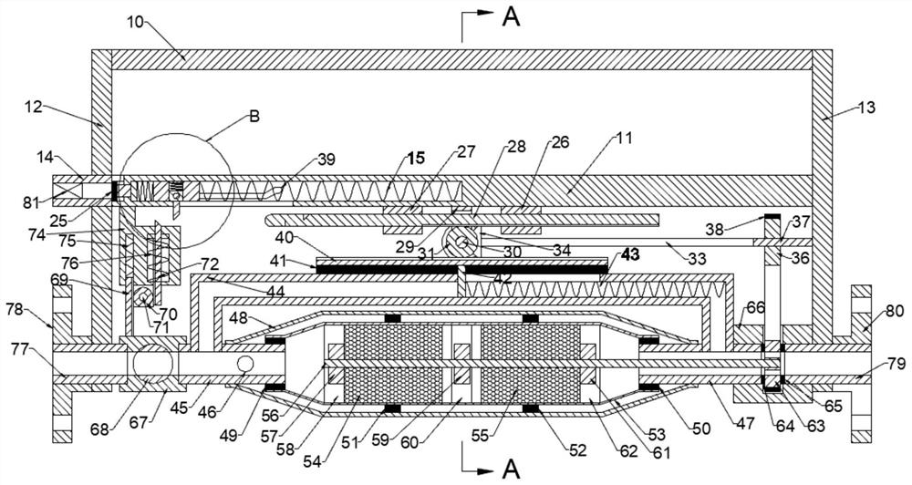
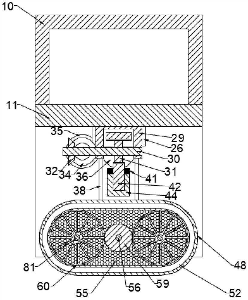
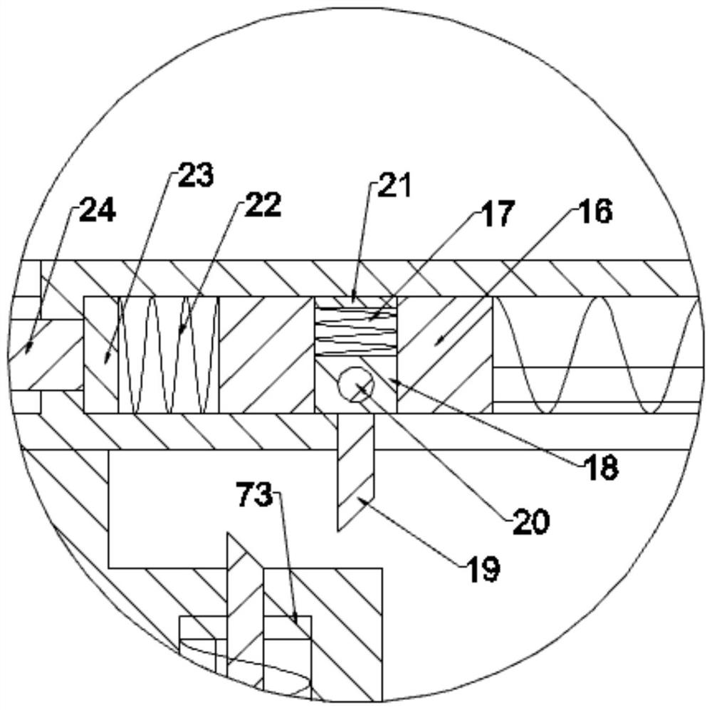
[0016] Combine below Figure 1-3 The present invention is described in detail, wherein, for the convenience of description, the orientations mentioned below are defined as follows: figure 1 The up, down, left, right, front and back directions of the projection relationship itself are the same.

[0017] combined with Figure 1-3 A three-way catalytic converter detection and cleaning device includes an upper case 10, the upper case 10 is fixedly connected to the left support plate 12, the upper case 10 is fixedly connected to the right support plate 13, and the upper case 10 is fixedly connected to the lower Shell 11, the left support plate 12 is fixedly connected to the water outlet pipe 14, the water outlet pipe 14 is fixedly connected to the left support plate 12, the lower shell 11 is connected to the valve spring 15, and the valve spring 15 is fixedly connected to the valve slider 16. The valve slider 16 is slidably connected to the lower shell 11, the valve slider 16 is ...


PUM


Abstract

The invention discloses a three-way catalyst detecting and cleaning device which comprises an upper shell. The upper shell is fixedly connected with a left supporting plate, the upper shell is fixedly connected with a right supporting plate, the upper shell is fixedly connected with a lower shell, the left supporting plate is fixedly connected with a water outlet pipe, the water outlet pipe is fixedly connected with the left supporting plate, and the lower shell is connected with a valve spring. The valve spring is fixedly connected with a valve sliding block, the valve sliding block is connected with the lower shell in a sliding mode, and the valve sliding block is connected with a pull rod sliding block in a sliding mode. According to the three-way catalyst detecting and cleaning device, detection of the blockage condition of a three-way catalyst and triggering of the device are achieved through a pressure detecting mechanism and a switch locking mechanism, so that a cleaning agent can be added in time when the three-way catalyst needs to be cleaned; and meanwhile, a rotary cleaning device arranged in the device can conduct rotary cleaning through the air pressure difference provided by tail gas, the cleaning effect is improved, and it is guaranteed that a cleaning agent is fully utilized.

Description

technical field [0001] The invention relates to the related technical field of automobile exhaust purification, in particular to a detection and cleaning device for a three-way catalytic converter. Background technique [0002] The three-way catalytic converter is the most important external purification device installed in the automobile exhaust system. It can convert harmful gases such as CO, HC and NOx emitted from automobile exhaust into harmless carbon dioxide, water and nitrogen through oxidation and reduction. , the three-way catalytic converter is easy to be blocked by oxide particles formed in the engine after being used for a period of time, which affects its conversion efficiency, and needs to be cleaned, but because the three-way catalytic converter is difficult to disassemble, cleaning is often difficult, and the cleaning agent needs to pass Fuel tank is added, and the cleaning operation is cumbersome. At the same time, it is difficult to observe the use of the ...

Claims


Application Information

Patent Timeline
IPC IPC(8): F01N11/00F01N13/00F01N3/10
CPCF01N3/101F01N11/00F01N13/00Y02T10/12Y02T10/40
Inventor 徐可阳
Owner 南京法洁安化妆品有限公司
Learn More