A Two-way Quick Action Large Flow Hydraulic Power Mechanism

A hydraulic power, large flow technology, applied in the direction of engine components, sliding valves, mechanical equipment, etc., can solve the problems of high dynamic response of hydraulic components, complex coordination adjustment, large reversing impact, etc., to simplify hydraulic control logic and facilitate Fast reciprocating motion, the effect of improving power output

Active Publication Date: 2021-12-07
TONGJI UNIV
View PDF7 Cites 0 Cited by
  • Summary
  • Abstract
  • Description
  • Claims
  • Application Information

AI Technical Summary

Problems solved by technology

The action control of the hydraulic actuator on the existing piling hammer is mostly controlled by a complex hydraulic system, and the action frequency and the stroke control method of the hydraulic cylinder are mostly realized by an additional mechanical restriction method, which has the advantages of large reversing impact and coordinated adjustment Complicated, the hydraulic components involved require a high dynamic response, a large number, and many fault points in the actual use process, etc.

Method used


Image

  • A Two-way Quick Action Large Flow Hydraulic Power Mechanism
  • A Two-way Quick Action Large Flow Hydraulic Power Mechanism
  • A Two-way Quick Action Large Flow Hydraulic Power Mechanism

Examples


Embodiment Construction

[0053] The present invention will be described in detail below in conjunction with the accompanying drawings and specific embodiments. This embodiment is carried out on the premise of the technical solution of the present invention, and detailed implementation and specific operation process are given, but the protection scope of the present invention is not limited to the following embodiments.

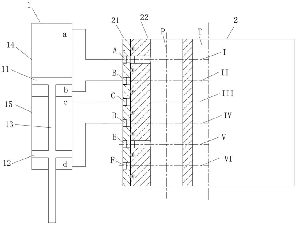
[0054] Such as figure 1 As shown, this embodiment provides a two-way fast-acting large-flow hydraulic power mechanism, which includes a hydraulic actuator 1 and a shaft distribution valve 2 connected to each other.

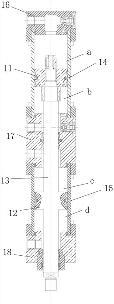
[0055] The hydraulic actuator 1 is a hydraulic cylinder with a double-piston structure, including a cylinder body, a front piston 11 and a rear piston 12 . Front piston 11 and rear piston 12 are arranged with piston rod 13. The cylinder body includes a front cylinder 14 and a rear cylinder 15, the front piston 11 is located in the front cylinder 14, and the front cylinder...


PUM


Abstract

The invention relates to a two-way quick-acting large-flow hydraulic power mechanism, which comprises an interconnected hydraulic actuator and a shaft distribution valve; the hydraulic actuator is a hydraulic cylinder with a double-piston structure, including a cylinder block, a front piston and a rear piston , the front piston and the rear piston are arranged on a piston rod, the cylinder body includes a front cylinder tube and a rear cylinder tube, the front piston is located in the front cylinder tube, and the front cylinder tube is divided into a first working chamber and a second working chamber, and the rear piston Located in the rear cylinder, the rear cylinder is divided into the third working chamber and the fourth working chamber; the shaft distribution valve includes the shaft distribution valve body stator and the shaft distribution valve core rotor, and the shaft distribution valve core rotor is provided with an oil supply channel and a return valve. The oil channel, the oil supply channel and the oil return channel are connected to the external pipeline, and the stator of the shaft distribution valve body and the rotor of the shaft distribution valve core are separated into four sealing areas by the sealing ring from top to bottom. Compared with the prior art, the present invention has the advantages of simplified hydraulic control logic, simple structure, convenient adjustment, convenient rapid reciprocating motion of the piston, and the like.

Description

technical field [0001] The invention relates to the technical field of hydraulic power mechanisms, in particular to a two-way fast-acting large-flow hydraulic power mechanism. Background technique [0002] Hydraulic piling hammers are widely used in the foundation construction of prefabricated piles such as bridges, buildings, ports and wharves. Compared with traditional diesel piling hammers, hydraulic piling hammers have the characteristics of high piling efficiency, no exhaust emissions, low noise, etc. Energy, wide adaptability, can be used for underwater piling and inclined pile driving, etc. Pile driving hammers include single-acting hydraulic hammers and double-acting hydraulic hammers. Single-acting hydraulic hammers mean that pile hammers fall freely under the action of their own weight, such as the HH357 series of British BSP and Model 650-3505 hydraulic hammers of American HPSI; The hydraulic hammer, that is, the pile hammer, falls at an acceleration greater than...

Claims


Application Information

Patent Timeline
Patent Type & Authority Patents(China)
IPC IPC(8): F15B13/02F15B13/042F15B15/14F15B15/22F16K11/085F16K3/26F16K3/314
CPCF15B13/021F15B13/0406F15B13/042F15B15/1404F15B15/149F15B15/225F15B2013/0413F16K3/262F16K3/314F16K11/0856
Inventor 訚耀保张玄李双路
Owner TONGJI UNIV
Why Eureka
Try Eureka