Multifunctional energy-saving resistance-free check valve applied to power station

A multi-functional, non-resistance technology, applied in functional valve types, valve details, control valves and other directions, it can solve the problems of troublesome check valve operation, poor lubrication effect, poor use intensity, etc., to achieve smooth movement, good anti-corrosion effect, Use high-intensity effects

Inactive Publication Date: 2021-06-18
SUZHOU KEDI FLUID CONTROL EQUIP
View PDF0 Cites 0 Cited by
  • Summary
  • Abstract
  • Description
  • Claims
  • Application Information

AI Technical Summary

Problems solved by technology

[0003] Existing multifunctional energy-saving non-resistance check valves have certain disadvantages in use. First, when in use, the operation of the check valve is relatively troublesome, the lubrication effect is poor, and there is a certain resistance when moving. It is beneficial to people's use, and it can't be well protected when it is used. The use strength is poor, the use function is less, and the structure is single, which brings certain adverse effects to people's use process. Therefore, we A multi-functional energy-saving non-resistance check valve applied to power stations is proposed

Method used


Image

  • Multifunctional energy-saving resistance-free check valve applied to power station
  • Multifunctional energy-saving resistance-free check valve applied to power station
  • Multifunctional energy-saving resistance-free check valve applied to power station

Examples


Embodiment 1

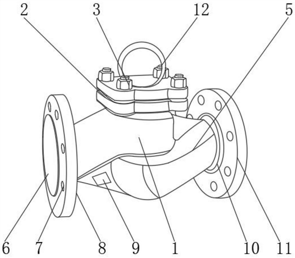
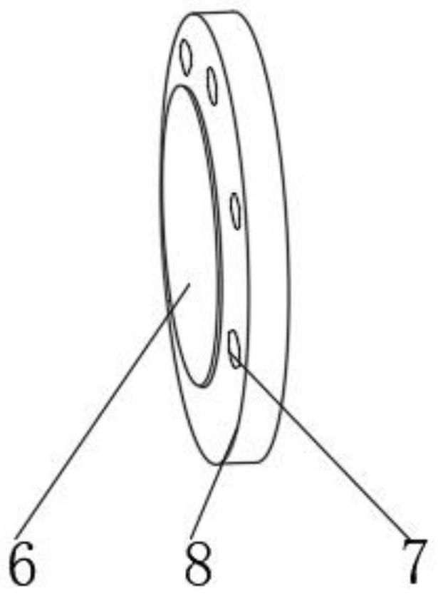
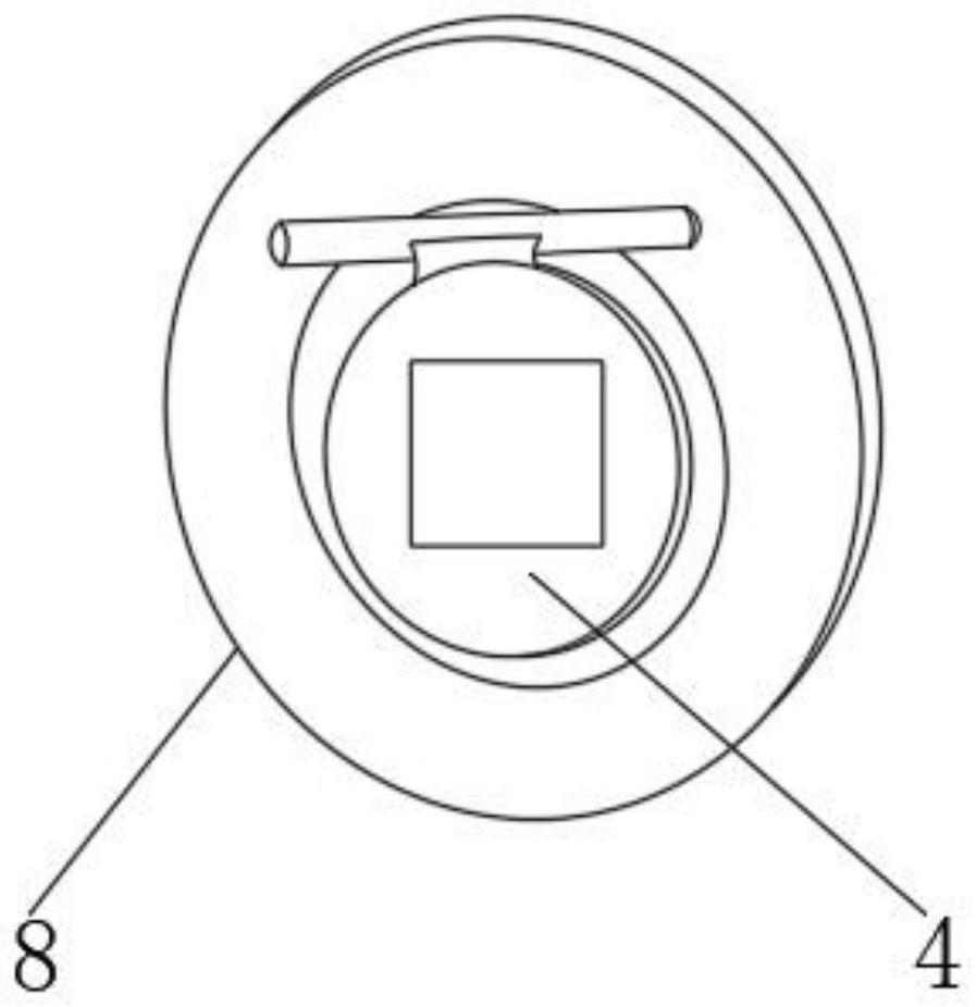
[0026] Such as Figure 1-4 As shown, a multifunctional energy-saving non-resistance non-return valve applied to power stations includes a valve body 1, the inner wall of the valve body 1 is fixedly connected with a reinforced anti-corrosion and anti-sticking mechanism 5, and one side of the valve body 1 is fixedly connected with a No. 1 installation valve seat 8, the other side of valve body 1 is fixedly connected with No. 2 installation valve seat 11, the inner wall of No. 1 installation valve seat 8 is provided with flow port 6, and the outer surface of No. 1 installation valve seat 8 is provided with positioning method Lan 7, a multifunctional monitoring mechanism 9 is installed on the outer side of the valve body 1, a welding block 10 is fixedly connected between the valve body 1 and the No. The upper end of 2 is equipped with a lifting ring 12, the four corners of the mounting seat 2 are positioned with mounting bolts 3, and the inner side of the No. 1 mounting valve seat...

Embodiment 2

[0030] On the basis of Example 1, as figure 1 , 5 As shown, a multifunctional energy-saving non-resistance non-return valve applied to power stations includes a valve body 1, the inner wall of the valve body 1 is fixedly connected with a reinforced anti-corrosion and anti-sticking mechanism 5, and one side of the valve body 1 is fixedly connected with a No. 1 installation valve seat 8, the other side of valve body 1 is fixedly connected with No. 2 installation valve seat 11, the inner wall of No. 1 installation valve seat 8 is provided with flow port 6, and the outer surface of No. 1 installation valve seat 8 is provided with positioning method Lan 7, a multifunctional monitoring mechanism 9 is installed on the outer side of the valve body 1, a welding block 10 is fixedly connected between the valve body 1 and the No. The upper end of 2 is equipped with a lifting ring 12, the four corners of the mounting seat 2 are positioned with mounting bolts 3, and the inner side of the N...

Embodiment 3

[0034] On the basis of Example 2, such as figure 1 , 6 As shown, a multifunctional energy-saving non-resistance non-return valve applied to power stations includes a valve body 1, the inner wall of the valve body 1 is fixedly connected with a reinforced anti-corrosion and anti-sticking mechanism 5, and one side of the valve body 1 is fixedly connected with a No. 1 installation valve seat 8, the other side of valve body 1 is fixedly connected with No. 2 installation valve seat 11, the inner wall of No. 1 installation valve seat 8 is provided with flow port 6, and the outer surface of No. 1 installation valve seat 8 is provided with positioning method Lan 7, a multifunctional monitoring mechanism 9 is installed on the outer side of the valve body 1, a welding block 10 is fixedly connected between the valve body 1 and the No. The upper end of 2 is equipped with a lifting ring 12, the four corners of the mounting seat 2 are positioned with mounting bolts 3, and the inner side of ...


PUM


Abstract

The invention discloses a multifunctional energy-saving resistance-free check valve applied to a power station. The multifunctional energy-saving resistance-free check valve comprises a valve body, the inner wall of the valve body is fixedly connected with a reinforced anti-corrosion and anti-sticking mechanism, one side of the valve body is fixedly connected with a first installation valve seat, and the other side of the valve body is fixedly connected with a second installation valve seat. A circulation opening is formed in the inner wall of the first installation valve seat, and a positioning flange is arranged on the outer side face of the first installation valve seat. According to the multifunctional energy-saving resistance-free check valve applied to the power station, a lubricating type adjustable check mechanism, the reinforced type anti-corrosion and anti-sticking mechanism and a multifunctional monitoring mechanism are arranged, fluid backflow stop operation can be conveniently and better conducted on the interior of a channel, the good lubricating effect is achieved, and resistance is almost zero. The use strength of the device can also be improved, the service life of the device can also be prolonged, the anti-corrosion effect is excellent, the internal use condition can be conveniently monitored, the use function of the device is increased, and better use prospects are brought.

Description

technical field [0001] The invention relates to the field of check valves, in particular to a multifunctional, energy-saving and non-resistance check valve applied to power stations. Background technique [0002] The multi-functional energy-saving non-resistance check valve is a supporting device for cutting off pipelines in power stations. Special valves for power stations will be used in power stations. It is suitable for pipelines of various systems in thermal power stations to cut off or connect pipeline media , It is more temperature-resistant and pressure-resistant than ordinary valves. With the continuous development of science and technology, people have higher and higher requirements for the manufacturing process of multi-functional energy-saving non-resistance check valves. [0003] Existing multifunctional energy-saving non-resistance check valves have certain disadvantages in use. First, when in use, the operation of the check valve is relatively troublesome, the...

Claims


Application Information

Patent Timeline
IPC IPC(8): F16K15/03F16K27/02F16K37/00
CPCF16K15/03F16K27/0209F16K37/0025F16K37/005
Inventor 田洪卫欧丹
Owner SUZHOU KEDI FLUID CONTROL EQUIP
Why Eureka
Try Eureka