
Strip lamp and manufacturing method of strip lamp

A manufacturing method and strip light technology, which are applied to the semiconductor devices of light-emitting elements, lighting devices, light sources, etc., can solve the problems of cumbersome, multi-assembly process of strip light structure parts, etc., to simplify the assembly process, simplify the structure, and reduce the quantity. Effect

Pending Publication Date: 2021-06-18
LEEDARSON IOT TECH INC
View PDF5 Cites 0 Cited by
  • Summary
  • Abstract
  • Description
  • Claims
  • Application Information

AI Technical Summary

Problems solved by technology

[0003] An object of the present application is to provide a strip light, aiming to solve the problem in the prior art that there are many structural parts of the strip light and the assembly process is cumbersome

Method used


Image

  • Strip lamp and manufacturing method of strip lamp
  • Strip lamp and manufacturing method of strip lamp
  • Strip lamp and manufacturing method of strip lamp

Examples


specific Embodiment approach

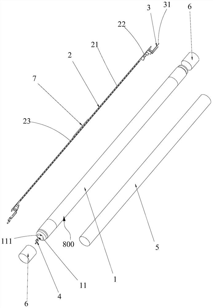
[0075] Further, see Figure 5 , as another specific embodiment of the manufacturing method of the strip light provided in the present application, the lamp tube 1 is a glass tube 800, and step S400 specifically includes the following steps:

[0076] S401, fixing the position of the metal wire 3 by a jig;

[0077] S403, heat and soften the openings of the two ends of the glass tube 800 (can be heated by spraying fire);

[0078] S404. After the two ends of the glass tube 800 are softened, clamp the softened part of the glass tube 800 and use the softened part to seal the opening of the glass tube 800, and make the softened part adhere to the metal wire 3, and Make the metal wire 3 extend out of the glass tube 800;

[0079] S405, forming the lamp cap 11 after cooling the softened part.

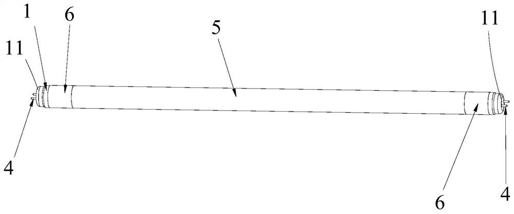
[0080] Please also refer to Figure 1-Figure 3 , that is, the lamp cap 11 is a "part" of the lamp tube 1. The lamp tube 1 is set as a glass tube 800, and the glass tube 800 is softened and cl...

Embodiment approach

[0081] Further, see Figure 5 , as another specific embodiment of the manufacturing method of the strip light provided in the present application, the metal wire 3 is a copper needle, and before step S403, the following steps are also included:

[0082] S402 , sleeve the molybdenum needle 4 on the outside of the metal wire 3 .

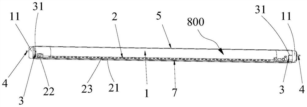
[0083] Please also refer to Figure 4 , when both the lamp tube 1 and the lamp cap 11 are glass parts, that is, the lamp tube 1 is a glass tube 800; when the lamp tube 1 and the lamp cap 11 are integrally formed, since the lamp cap 11 is formed of a glass part and bonded to the surface of the metal wire 3, The metal wire 3 is a copper needle, and the shrinkage rate of the copper needle and the glass material is different, so the glass is easy to crack when the copper needle is heated and expanded. The shrinkage ratio of the molybdenum material and the glass material is almost the same, so that the outer wall of the molybdenum needle 4 is set in conta...


PUM


Abstract

The invention discloses a strip lamp and a manufacturing method of the strip lamp. The strip lamp comprises a lamp tube, a driving power supply panel installed in the lamp tube and metal wires located at the two opposite ends of the driving power supply panel. The far ends, away from the driving power supply panel, of the metal wires are located outside the lamp tube. The driving power supply panel comprises a printed circuit board, a driving element arranged on the printed circuit board and electrically connected with the metal wires, and a light-emitting part arranged on the printed circuit board. The driving power supply board can be used as an independent part of the strip lamp, the structure of the strip lamp is effectively simplified, the number of strip lamp structural parts is reduced, only the driving power supply board needs to be installed in the lamp tube during assembly, and compared with the prior art that a light source board is installed in the lamp tube firstly, then a driving board is installed in a lamp cap, and then the lamp cap is fixed on the lamp tube, the disclosed strip lamp has an advantage that the assembly process of the strip lamp is effectively simplified.

Description

technical field [0001] The present application relates to the field of lighting equipment, in particular to a bar light and a method for making the bar light. Background technique [0002] The main body of the existing light bar is generally composed of a lamp tube and a lamp holder. The lamp tube is equipped with a light source board, and the lamp holder is equipped with a drive board. The electrical connection between the drive board and the copper pin is terminal connection. This kind of structure is connected through more structural parts and original devices, the assembly process is cumbersome, the assembly time is long, and more manual operations are required. The labor cost is high, and the quality stability of the product after assembly is poor. Contents of the invention [0003] An object of the present application is to provide a light bar, aiming at solving the problem in the prior art that there are many structural parts of the light bar and the assembly proce...

Claims


Application Information

Patent Timeline
IPC IPC(8): F21K9/90F21Y115/10
CPCF21K9/90F21Y2115/10
Inventor 曹亮亮许金
Owner LEEDARSON IOT TECH INC
Features
  • Generate Ideas
  • Intellectual Property
  • Life Sciences
  • Materials
  • Tech Scout
  • Unparalleled Data Quality
  • Higher Quality Content
  • 60% Fewer Hallucinations
Learn More