Internal spiral heat exchanger

A heat exchanger, spiral technology, applied in the field of internal spiral heat exchangers, can solve the problems of height, fins can only be installed on the outer wall of the tube, overall performance is limited by conditions, unfavorable heat exchange, etc., to achieve product size The effect of high precision, increased length and area, and improved heat transfer efficiency

Pending Publication Date: 2021-06-18
SHUNDE POLYTECHNIC
View PDF1 Cites 0 Cited by
  • Summary
  • Abstract
  • Description
  • Claims
  • Application Information

AI Technical Summary

Problems solved by technology

[0003] On the other hand, when the fluid flows in the pipe, it is easy to form a laminar flow phenomenon on the pipe wall, that is, the fluid particles always move in the direction parallel to the pipe, and the particles do not mix with each other, and the fluid flows on the pipe wall or even in the entire pipe. For example, layers of concentric cylinders are flowing in parallel, obviously, this is not conducive to heat exchange
In order to destroy the laminar flow phenomenon of the fluid and improve the heat transfer performance of the heat exchanger, CN200810231358.X discloses a self-supporting heat exchanger with spiral fins, which has spiral fins welded on each heat exchange tube. The function of supporting the heat exchange tube can also disturb the flow, forcing the fluid to do a spiral flow along the surface of the tube, which increases the disturbance of the fluid and improves the heat transfer coefficient. The fluid generally flows longitudinally in the shell side of the heat exchanger, but its ribs The pitch of the fins is relatively large and the distance between the fins and the tube is the same height. The fins can only be installed on the outer wall of the tube, so that the overall performance is limited by conditions, and its structure and performance need to be further improved and improved.

Method used


Image

  • Internal spiral heat exchanger
  • Internal spiral heat exchanger
  • Internal spiral heat exchanger

Examples


Embodiment Construction

[0022] The technical solution will be described in detail below with reference to specific embodiments.

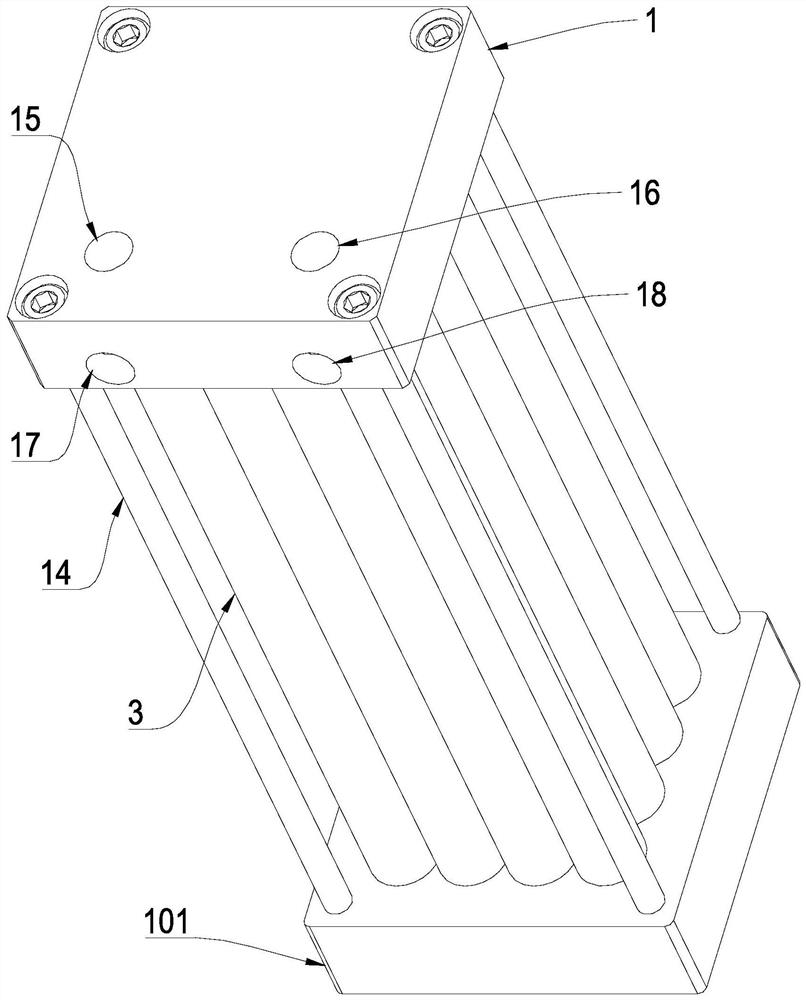
[0023] like Figure 1-3 As shown, the present invention discloses an internal spiral heat exchanger, which includes an upper cover 1 and a base 101, and is connected to a middle section between the upper cover 1 and the base 101, wherein 16 middle sections are selected, and they are 4×4 The array is vertically arranged between the upper cover 1 and the base 101, and two independent heat exchange channels are formed between the upper cover 1, the base 2 and the middle section, which are the refrigerant flow channel 32 and the refrigerant flow channel 24 respectively. .

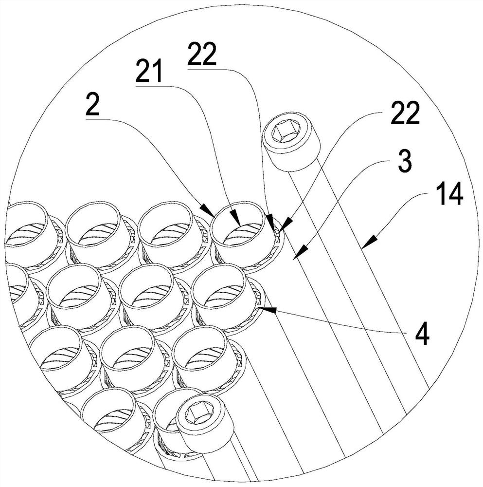
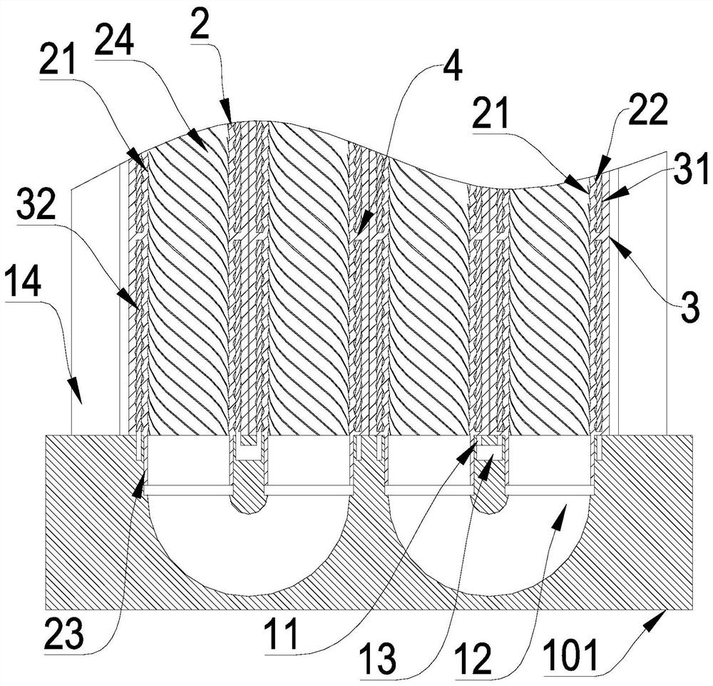
[0024] Further, the middle section includes an inner tube 2 and an outer sleeve 3. The upper cover 1 and the base 101 are provided with a bend 12 opening on the upper cover 1 and the base 101, and on the upper cover 1 and the base 101. A ring groove 11 is arranged around the opening of the bend 12 on the ...


PUM


Abstract

The invention discloses an internal spiral heat exchanger. The heat exchanger comprises an upper cover, a base and middle sections connected between the upper cover and the base, each middle section comprises an inner pipe and an outer sleeve, the upper cover and the base are provided with elbows with openings formed in the plate face of the upper cover and the plate face of the base, annular grooves are formed in the plate face of the upper cover and the plate face of the base and surround the opening portions of the elbows, openings in the two ends of the elbows are connected with the inner pipes of the adjacent middle section, interlayers are formed among the outer sleeves, the inner pipes and the annular grooves, communicating cavities are formed in the upper cover and the base to enable the two adjacent interlayers close to the elbows to communicate, the upper cover and the base are formed through metal injection molding, first threaded ribs are arranged on the inner wall face of the inner pipes, the thread pitch L1 of the first threaded ribs meets the condition that L1 is smaller than 0.028 Re*D1, Reynolds number Re=, v is the average flow velocity of fluid on the inner walls of the inner pipes, D1 is the diameter of the inner walls of the inner pipes, and mu is the current kinematic viscosity coefficient of the fluid on the inner walls of the inner pipes. A roundabout heat exchange structure with a long route is formed in the heat exchanger, and sufficient heat exchange between a refrigerant and a secondary refrigerant can be achieved.

Description

technical field [0001] The invention relates to the technical field of heat exchange equipment, and more particularly, to an internal spiral heat exchanger. Background technique [0002] The existing heat exchanger is arranged in the space in a coiled form through the casing formed by the inner pipe and the main pipe. There is a refrigerant in the interlayer space of the casing between the inner pipe and the main pipe, and there is a refrigerant in the inner pipe. For heat exchange with the refrigerant, the inner tube wall is used as the isolation material between the inner tube inner space and the casing interlayer space, and generally a metal with good heat conduction such as copper is used as the heat conduction metal. The inner tube is coiled in parallel with the main tube in the main tube, and the gap between the outer wall of the inner tube and the inner wall of the main tube, that is, the interlayer space, must be kept uniform. Plus turbulent structures. The end of ...

Claims


Application Information

Patent Timeline
Patent Type & Authority Applications(China)
IPC IPC(8): F28D7/10F28F9/26F28F9/02F28F1/08F28F21/08B22F3/22
CPCB22F3/22F28D7/106F28F1/08F28F9/0229F28F9/26F28F21/08
Inventor 余华明畅国帏李东洺
Owner SHUNDE POLYTECHNIC
Why Eureka
Try Eureka