Double-sided alignment fitting precision detection system

A precision detection and fitting technology, applied in measuring devices, instruments, optical devices, etc., can solve problems such as insufficient light, reduced photo clarity, and positioning failures.

Inactive Publication Date: 2021-06-18
武汉先河激光技术有限公司
View PDF3 Cites 0 Cited by
  • Summary
  • Abstract
  • Description
  • Claims
  • Application Information

AI Technical Summary

Problems solved by technology

[0003] During the alignment process of the existing laminating machine using the camera, the problem of insufficient light usually occurs due to environmental influences. When the light is too low, the clarity of the photos taken will be greatly reduced, and it cannot be recognized by software, which eventually leads to positioning failure.

Method used


Image

  • Double-sided alignment fitting precision detection system
  • Double-sided alignment fitting precision detection system
  • Double-sided alignment fitting precision detection system

Examples


Embodiment 1

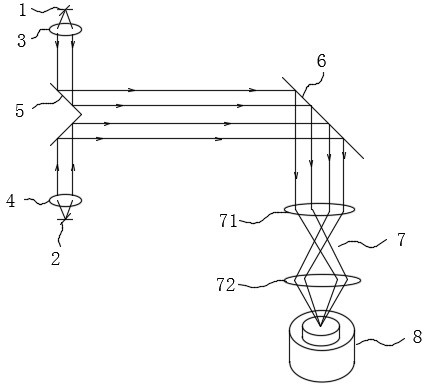
[0025] Example 1, such as figure 2 As shown, the present invention provides a double-sided alignment and bonding accuracy detection system, including: a light collimation device, an optical path conversion device, and an imaging device. Collimating device 2, the light collimating device 1 and the light collimating device 2 are used to collimate divergent light into parallel light; the optical path conversion device is arranged between the light collimating device 1 and the light collimating device 2 In between, the optical path conversion device is used to adjust the angle of the light collimated by the light collimating device 1 and the light collimating device 2 so that the emitted light is parallel to the collimated light; the imaging device is set On one side of the optical path conversion device, the imaging device is used to receive the light emitted by the optical path conversion device for imaging.

[0026] In an embodiment of the present invention, the light collima...

Embodiment 2

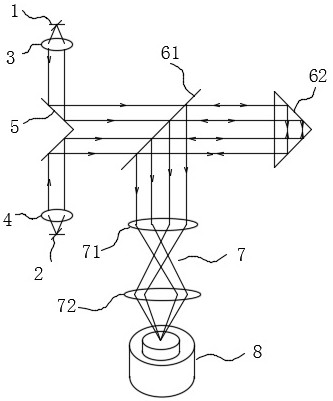
[0029] Example 2, such as image 3As shown, the present invention provides another double-sided aligning and adhering accuracy detection system. The difference from Embodiment 1 is that the light deflection element 2 includes a half mirror 61 and a triangular prism 62. The half mirror The reflection mirror 61 can direct the light emitted by the first reflection mirror 5 to the triangular prism 62 , and can also deflect the light reflected by the triangular prism 62 by 90 degrees and emit it to the imaging device. Specifically, the triangular prism 62 includes a transmission surface, a reflection surface 1, and a reflection surface 2, a certain angle is formed between the reflection surface 1 and the reflection surface 2, and the transmission surface faces the half mirror 61; it can be understood that the triangular prism 62 is an isosceles right-angle triangular prism, that is to say, the included angle between the first reflecting surface and the second reflecting surface is ...


PUM


Abstract

The invention provides a double-sided alignment fitting precision detection system, which comprises a light collimation device, a light path conversion device and an imaging device; the light collimation device comprises a first light collimation device and a second light collimation device which are oppositely arranged, and the first light collimation device and the second light collimation device are used for collimating divergent light into parallel light; the light path conversion device is arranged between the first light collimation device and the second light collimation device, and the light path conversion device is used for performing angle adjustment on the light collimated by the first light collimation device and the second light collimation device so as to enable the emitted light to be parallel to the collimated light; the imaging device is arranged on one side of the light path conversion device, and the imaging device is used for receiving the light emitted by the light path conversion device for imaging. The double-surface alignment fitting precision detection system provided by the invention is simple in structure and convenient to operate, and can detect the alignment conditions of the upper and lower surfaces of the to-be-fitted part at the same time.

Description

technical field [0001] The invention relates to the technical field of precision bonding equipment, in particular to a double-sided positioning bonding precision detection system. Background technique [0002] With the rapid development of precision instruments, people have increasingly strong requirements for the accuracy and efficiency of processing technology. Among them, the application of PI film copper-clad laminates is becoming more and more extensive. The corresponding patterns are made on the substrate of the flexible PI film, and the corresponding patterns are laminated on the copper-clad laminates. The manufacturing process is simple and convenient. In order to process and fit products efficiently, when assembling, it is necessary to accurately position and perfectly fit external workpieces or electronic components, so as to improve product production efficiency and ensure product yield. [0003] During the alignment process of the existing laminating machine usi...

Claims


Application Information

Patent Timeline
Patent Type & Authority Applications(China)
IPC IPC(8): G01B11/00
CPCG01B11/00
Inventor 段光前陈秀峰陈中华黄树平童杰
Owner 武汉先河激光技术有限公司
Why Eureka
Try Eureka