Light source packaging structure, packaging technology and LED bulb
A packaging structure and light source technology, applied in the field of lighting, can solve problems such as heat dissipation defects of LED lamps, and achieve the effects of large power controllable range, small size, and improved heat dissipation effect
- Summary
- Abstract
- Description
- Claims
- Application Information
AI Technical Summary
Problems solved by technology
Method used
Image
Examples
Embodiment 1
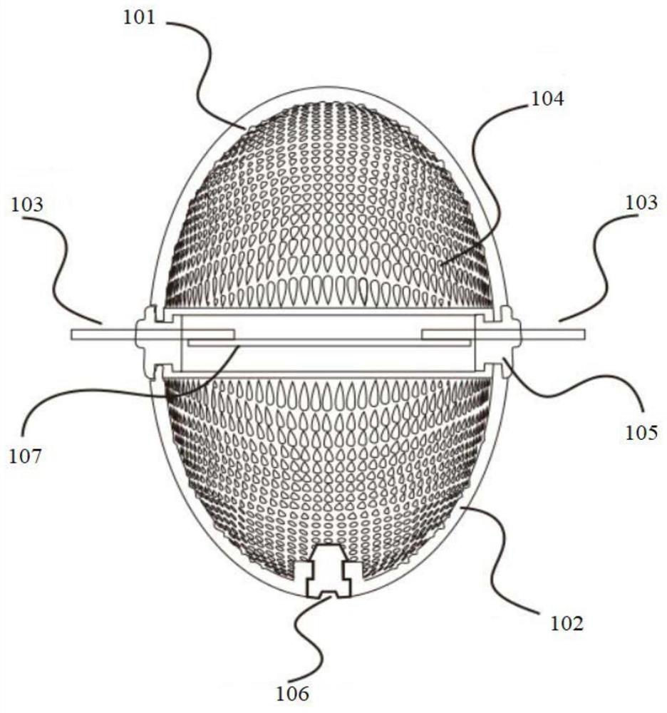
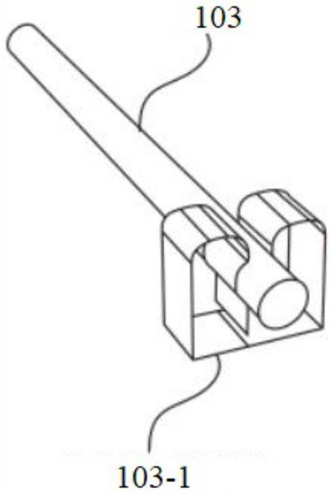
[0049] Such as figure 1 As shown, a light source package structure includes a light-transmitting first package shell 101 and a second package shell 102, the first package shell 101 and the second package shell 102 are connected to form a sealed cavity A, and the sealed cavity A is filled with a heat conducting liquid or a heat conducting gas; a light source is provided in the sealed cavity A, and the light source includes conductive pins 103 , and the conductive pins protrude from the sealed cavity A to the outer space of the sealed cavity A.
[0050] Grooves 104 are provided on the inner surfaces of the first packaging case 101 and the second packaging case 102 . The outer surfaces of the first packaging case 101 and the second packaging case 102 are smooth surfaces. The grooves and protrusions can be evenly distributed or regularly unevenly distributed.
[0051] In other executable embodiments, protrusions are provided on the inner surfaces of the first packaging case 101 ...
Embodiment 2
[0071] An LED light source encapsulation process, which is used to manufacture the light source encapsulation structure described in Embodiment 1, said process comprising the following steps:
[0072] setting a valve in the first packaging case or the second packaging case;
[0073] Fill fluorescent glue on the inner surfaces of the first packaging case and the second packaging case, and dry them;
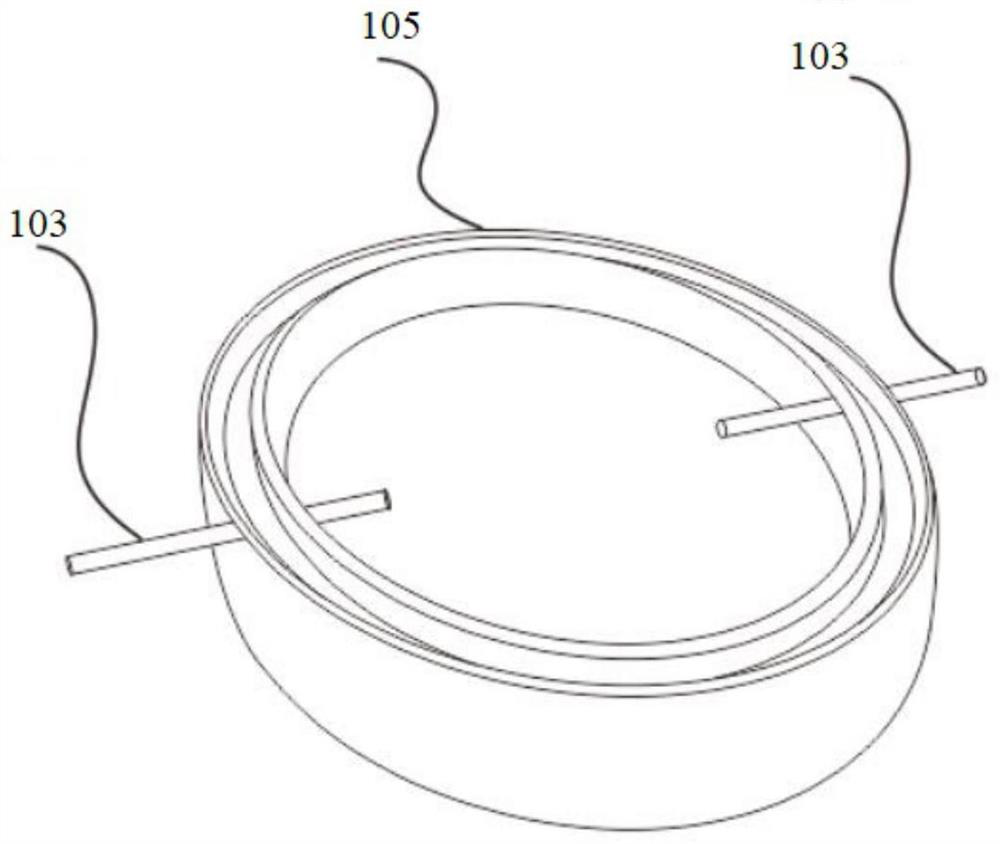
[0074] The intermediate ring 105 is placed between the first packaging case and the second packaging case, and the first packaging case, the second packaging case and the intermediate ring 105 are sealed and fixed by a sealing process to form a sealed cavity;
[0075] The sealed chamber is vacuumed through the valve and then filled with heat-conducting gas or liquid, and then the valve is sealed.
[0076] Wherein, the conductive pins are integrally formed by injection molding to form the intermediate ring 105 .
[0077] Specifically, the sealing process adopts ultrasonic sealing,...
Embodiment 3
[0079] An LED light bulb, comprising at least one light source encapsulation structure described in Embodiment 1, a sealed bulb is provided outside the light source encapsulation structure, a sealed cavity B is formed between the bulb and the light source encapsulation structure, the The sealed chamber B is filled with heat-conducting gas or heat-conducting liquid. It also includes a stem, a lamp cap and a conductive wire, the lamp cap and the stem are connected to the bulb, the lamp cap is used to connect to an external power supply, the conductive wire is connected to the lamp cap and the stem, and the conductive wire of the light source packaging structure The pins are connected to the conductive wires.
[0080] In one application implementation, the sealed cavity A can be considered as a cavity for placing the light source, and the sealed cavity B formed by the bulb is a protective cavity or a secondary heat dissipation cavity.
[0081] Such as Figure 6-9 Four light sou...
PUM
 Abstract
Description
Claims
Application Information
 - R&D
- Intellectual Property
- Life Sciences
- Materials
- Tech Scout
- Unparalleled Data Quality
- Higher Quality Content
- 60% Fewer Hallucinations
Browse by: Latest US Patents, China's latest patents, Technical Efficacy Thesaurus, Application Domain, Technology Topic, Popular Technical Reports.
© 2025 PatSnap. All rights reserved.Legal|Privacy policy|Modern Slavery Act Transparency Statement|Sitemap|About US| Contact US: help@patsnap.com


