Light-emitting device and bulb

A light-emitting device and light bulb technology, applied in the field of lighting, can solve the problems of low light efficiency, burnt P-N junction, and decreased luminous efficiency, and achieve the effects of small size, large power controllable range, and improved heat dissipation effect

Pending Publication Date: 2022-05-10
HANGZHOU HANGKE OPTOELECTRONICS
View PDF0 Cites 0 Cited by
  • Summary
  • Abstract
  • Description
  • Claims
  • Application Information

AI Technical Summary

Problems solved by technology

However, due to the influence of the nature of the filament, the conventional straight hard filament has limitations in the shape of the filament lamp. Although the flexible filament can be made into different shapes, it has the flaws of low luminous flux and low luminous efficiency.
[0005] In order to achieve a light distribution effect close to that of an incandescent lamp and improve light efficiency, its heat dissipation problem is also a problem that needs to be solved. LED is a semiconductor device, and the rise of the junction temperature of its P-N junction will lead to a rapid decline in luminous efficiency, or even burn the P-N junction. Junction; This type of low-voltage high-current power LED lighting, including LED filament lamps, until today, the problem of heat dissipation is still a long-term problem that needs to be solved

Method used


Image

  • Light-emitting device and bulb
  • Light-emitting device and bulb
  • Light-emitting device and bulb

Examples


Embodiment 1

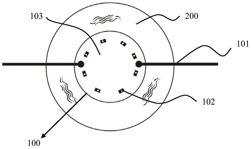
[0042] a lighting device such as figure 1 , including a light engine structure, the light engine includes a light source 100 and a first sealed cavity 200, the light source is placed in the first sealed cavity, the first sealed cavity is filled with insulating liquid, the first sealed cavity The light source in the cavity is exposed to the insulating liquid; a second sealed cavity 300 is provided outside the first sealed cavity, and the second sealed cavity is filled with insulating gas;

[0043] The light source includes pins 101, and the pins protrude from the first sealed cavity to the second sealed cavity;

[0044] The first sealed cavity is a translucent, light-transmitting sealed cavity, and the second sealed cavity is a fully transparent, light-transmitted sealed cavity. The light transmission performance of translucent and light-transmitting materials is equivalent to that of transparent materials, but the translucent material can reduce the glare of the light source....

Embodiment 2

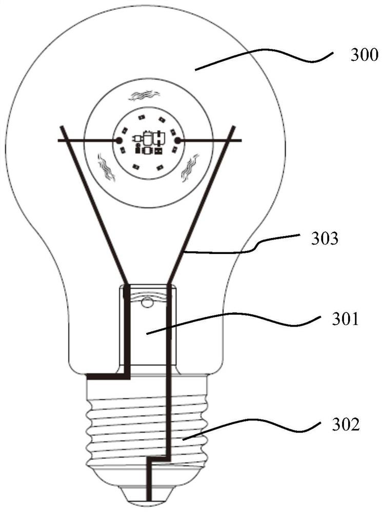
[0065] This embodiment discloses a light bulb, such as image 3 , the light bulb structure includes the light-emitting device described in Embodiment 1, and also includes a stem 301 and a lamp cap 302, and the lamp cap and the stem are connected to the housing of the second sealed cavity 300 (ie, the bulb of the bulb), and the lamp cap For accessing an external power supply, the casing of the first sealed chamber is fixed to the stem.

[0066] The stem includes a horn tube, a horn base, an electrical lead-out wire and an exhaust pipe, the exhaust pipe is placed in the horn tube, the horn base is sealed and connected to the second sealed cavity, and one end of the electrical lead-out wire is connected to to the lamp head, and the other end is connected to the pin.

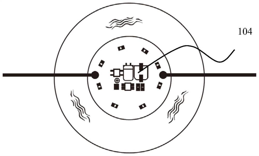
[0067] In another embodiment, the driving circuit is placed in the second sealed cavity, and one end of the pin located in the second sealed cavity is connected to the driving circuit.

[0068] Or, in another embo...

Embodiment 3

[0071] like Figure 4 , several bare crystal structures are connected in series or in parallel or combined in series and parallel to form a chain light source 400, the chain light source is wound around the main substrate 401 to realize a 4Π light emitting (360° omnidirectional light emitting) mode, and the main substrate can be shielded in the chain In the middle of the light source. A specific implementation is as follows:

[0072] The chain light source includes several strip-shaped substrates, on which a plurality of connecting lines are arranged, and each connecting line is a bare crystal structure connected in series or in parallel or a combination of series and parallel, thereby forming a filament structure. The chain light sources on each strip substrate can be light sources with the same color temperature or different color temperature light sources. Each connecting line is independently controlled for controlling the filament to emit light of a specific color. Spe...


PUM


Abstract

The light-emitting device comprises a light engine structure, the light engine structure comprises a light source and a first sealing cavity, the light source is arranged in the first sealing cavity, the first sealing cavity is filled with insulating liquid or gas, and the light source in the first sealing cavity is exposed in the insulating liquid or gas; a second sealing cavity is arranged outside the first sealing cavity, and the second sealing cavity is filled with insulating liquid or gas; according to the sealed light-emitting engine injected with the heat dissipation liquid or gas, a second-layer sealed heat dissipation structure is arranged outside the light-emitting engine, meanwhile, a light source adopts an LED bare crystal structure exposed to the heat dissipation liquid or gas, the heat dissipation problem of an LED lamp is well solved, meanwhile, the concept design of the light engine is adopted, and the heat dissipation effect is good. A foundation is provided for various applications of the LED bulb lamp, and the defects of cost and lighting effect of the common bulb lamp at present are overcome.

Description

technical field [0001] The invention belongs to the technical field of lighting, and in particular relates to an LED lighting device and a light bulb. Background technique [0002] Light-emitting diodes (Light-Emitting Diode, referred to as "LED") are widely used in display, general lighting and other fields due to their characteristics of energy saving, environmental protection, long life, and small size. The technology of the LED industry is becoming more and more mature, the application is becoming wider and wider, the market demand is large, and it is gradually replacing the traditional high-voltage halogen lamps, tungsten lamps, and even energy-saving lamps to achieve real energy-saving and emission-reducing greening of the earth. At present, in order to meet the needs of different application fields, LED packaging technology is constantly improving, and the form of LED light source is becoming more and more diversified. [0003] Traditional bead-type LED lights, becau...

Claims


Application Information

Patent Timeline
Patent Type & Authority Applications(China)
IPC IPC(8): F21K9/00F21V31/00F21V29/503F21V29/56F21V19/00F21V23/00F21K9/69F21K9/68F21K9/64F21K9/232F21K9/238F21Y115/10
CPCF21K9/00F21V31/005F21V29/503F21V29/56F21V19/0025F21V23/003F21K9/69F21K9/68F21K9/64F21K9/232F21K9/238F21Y2115/10F21V29/85F21Y2107/70F21Y2103/10F21V23/005
Inventor 严钱军郑昭章马玲莉
Owner HANGZHOU HANGKE OPTOELECTRONICS
Why Eureka
Try Eureka