Supercharge Your Innovation With Domain-Expert AI Agents!

Flyback switching circuit and control method thereof

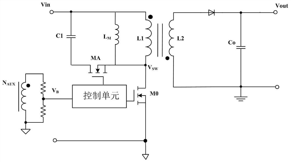
A technology of flyback switch and switch control unit, which is applied in the direction of control/regulation system, electrical components, and regulation of electrical variables, etc., which can solve the problems of low system efficiency and large turn-on loss of the main power switch tube, so as to improve system efficiency and reduce The effect of enabling power consumption

Inactive Publication Date: 2021-06-18
JOULWATT TECH INC LTD
View PDF0 Cites 2 Cited by
  • Summary
  • Abstract
  • Description
  • Claims
  • Application Information

AI Technical Summary

Problems solved by technology

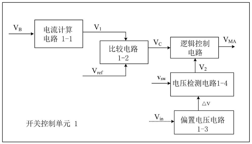
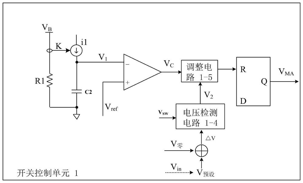
[0004] In view of this, the purpose of the present invention is to provide a method to reduce the turn-on loss of the main power switch tube by adjusting the turn-off time of the first switch tube, so as to solve the problem of large turn-on loss of the main power switch tube in the flyback switch circuit in the prior art, Technical problems with low system efficiency

Method used


Image

  • Flyback switching circuit and control method thereof
  • Flyback switching circuit and control method thereof
  • Flyback switching circuit and control method thereof

Examples


Embodiment Construction

[0038] Preferred embodiments of the present invention will be described in detail below with reference to the accompanying drawings, but the present invention is not limited to these embodiments. The present invention covers any alternatives, modifications, equivalent methods and schemes made within the spirit and scope of the present invention.

[0039] In order to provide the public with a thorough understanding of the present invention, specific details are set forth in the following preferred embodiments of the present invention, but those skilled in the art can fully understand the present invention without the description of these details.

[0040] In the following paragraphs the invention is described more specifically by way of example with reference to the accompanying drawings. It should be noted that all the drawings are in simplified form and use inaccurate scales, which are only used to facilitate and clearly assist the purpose of illustrating the embodiments of t...


PUM


Abstract

The invention discloses a flyback switching circuit and a control method thereof. A bias voltage signal greater than zero is set, and the bias voltage signal greater than zero is used for controlling the turn-off time of a first switching tube in the flyback switching circuit. Before a main power switching tube of the flyback switching circuit is turned on, the drain-source voltage of the main power switch tube is consistent with the bias voltage signal so that the switching-on power consumption of the main power switch tube is reduced, and the system efficiency is improved.

Description

technical field [0001] The invention relates to the technical field of power electronics, and more specifically, to a flyback switch circuit and a control method thereof. Background technique [0002] The flyback switching circuit includes a main power switch tube, which provides energy to the load through the on and off of the main power switch tube. The switch control of the main power switch tube is the control core of the switch circuit. How to effectively control the switching state of the main power switch tube It is a very challenging job. [0003] In the prior art active clamp flyback switching power supply, a clamp capacitor is connected between the drain of the main power switch tube and the input terminal, and a clamp switch is connected between the drain of the main power switch tube and the capacitor. Tube, the clamp switch tube conducts at a certain moment during the off period of the main power switch tube, and does not conduct during the period when the main...

Claims


Application Information

Patent Timeline
IPC IPC(8): H02M3/335H02M1/08
CPCH02M3/335H02M1/08Y02B70/10
Inventor 黄必亮
Owner JOULWATT TECH INC LTD
Features
  • R&D
  • Intellectual Property
  • Life Sciences
  • Materials
  • Tech Scout
  • Unparalleled Data Quality
  • Higher Quality Content
  • 60% Fewer Hallucinations
Learn More