
Clock frequency divider based on switched capacitor, microcontroller and phase-locked loop circuit

A clock divider, switched capacitor technology, applied in the direction of automatic power control, electrical components, pulse counters, etc., can solve the problems of complex circuit implementation, difficult to achieve fractional frequency division, etc., and achieve the effect of flexible adjustment of frequency division coefficients

Active Publication Date: 2021-06-18
上海灵动微电子股份有限公司
View PDF18 Cites 0 Cited by
  • Summary
  • Abstract
  • Description
  • Claims
  • Application Information

AI Technical Summary

Problems solved by technology

If any integer frequency division is required, circuit entities such as digital comparators need to be added, and if decimal or fractional frequency division is required, the circuit implementation is more complicated
At the same time, due to the characteristics of digital circuits, it is determined that the frequency-divided clock can only achieve fractional frequency division in the average sense, and it is difficult to achieve period-to-cycle fractional frequency division, that is, the frequency of the frequency-divided clock and the frequency-divided clock The fractional frequency division relationship only exists on the basis of long-term average, and it is impossible to achieve a perfect fractional frequency division relationship for each cycle clock

Method used


Image

  • Clock frequency divider based on switched capacitor, microcontroller and phase-locked loop circuit
  • Clock frequency divider based on switched capacitor, microcontroller and phase-locked loop circuit
  • Clock frequency divider based on switched capacitor, microcontroller and phase-locked loop circuit

Examples


Embodiment Construction

[0023] In the following description, many technical details are proposed in order to enable readers to better understand the application. However, those skilled in the art can understand that the technical solutions claimed in this application can be realized even without these technical details and various changes and modifications based on the following implementation modes.

[0024] In order to make the purpose, technical solution and advantages of the present application clearer, the implementation manner of the present application will be further described in detail below in conjunction with the accompanying drawings.

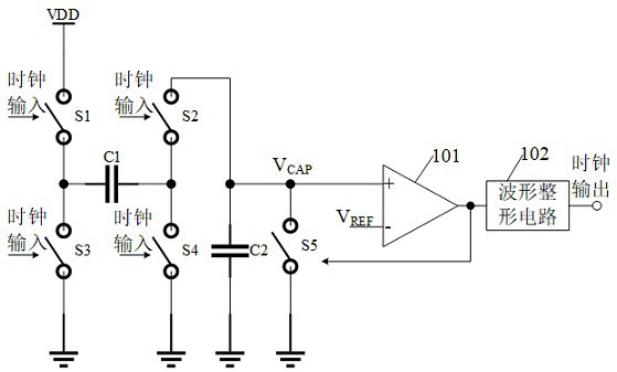
[0025] The first embodiment of the present application discloses a clock divider based on switched capacitors, figure 1 A schematic structural diagram of the clock divider is shown. The clock divider includes: first to fifth switches S1 - S5 , a first capacitor C1 , a second capacitor C2 and a comparator 101 . One end of the first capacitor C1 is coupled...


PUM


Abstract

The invention relates to the technical field of integrated circuits, and provides a clock frequency divider based on switched capacitors, which comprises first to fifth switches, a first capacitor, a second capacitor and a comparator, and the capacitance value of the second capacitor is greater than that of the first capacitor. One end of the first capacitor is coupled to one end of the first switch and one end of the third switch, the other end of the first switch is coupled with a power supply, and the other end of the first capacitor is coupled to one end of the second switch and one end of the fourth switch; one end of the second capacitor is coupled to the other end of the second switch, one end of the fifth switch and the first input end of the comparator, the second input end of the comparator is coupled with the reference voltage, and the other ends of the third to fifth switches are coupled with the ground end; the first switch and the second switch are controlled by a first clock signal, the third switch and the fourth switch are controlled by a second clock signal, and the first clock signal and the second clock signal are a pair of inverted clock signals; and the state of the fifth switch is controlled through an output signal of the comparator. According to the invention, frequency division of any coefficient can be realized.

Description

technical field [0001] The present application relates to the field of integrated circuits, and further relates to a clock frequency divider based on switched capacitors, a microcontroller and a phase-locked loop circuit using the clock frequency divider. Background technique [0002] Clock divider circuits are common in the design of integrated circuits. In integrated circuits, due to cost considerations, the number of clock sources is usually limited; and different internal circuit modules usually have different clock frequency requirements; the clock frequency division circuit is to solve the problem of using a small number of clock sources to provide different clock frequencies. Application scenarios. [0003] Common clock frequency division circuits are mostly digital circuits, which are composed of N-level D flip-flops and 1-bit full adders cascaded, and the output terminals of each level of D flip-flops are divided by 2, 4, 8... times of the input clock . If it is ...

Claims


Application Information

Patent Timeline
Patent Type & Authority Applications(China)
IPC IPC(8): H03K23/64H03K23/68H03L7/183
CPCH03K23/64H03K23/68H03L7/183
Inventor 邱子晨孟豪吴忠洁
Owner 上海灵动微电子股份有限公司
Learn More