
Oil stain cleaning agent processing equipment for environmental protection equipment

A technology of environmental protection equipment and processing equipment, applied in mixers, dissolving, chemical instruments and methods, etc., can solve the problems of difficulty in removing powdery raw materials, waste of raw materials, etc.

Active Publication Date: 2021-06-22
济南一诺润滑油有限公司
View PDF2 Cites 1 Cited by
  • Summary
  • Abstract
  • Description
  • Claims
  • Application Information

AI Technical Summary

Problems solved by technology

[0003] Since the oily cleaning agent for environmental protection equipment is made of powdery raw materials, the powdery raw material is easy to adhere to the inner wall of the conical feeding hopper when it is introduced into the oily cleaning agent for environmental protection equipment. If it is put into the oil cleaning agent blending machine for environmental protection equipment, the powdery raw materials will continue to adhere to the inner wall of the hopper and it will be difficult to remove, which will lead to waste of raw materials

Method used


Image

  • Oil stain cleaning agent processing equipment for environmental protection equipment
  • Oil stain cleaning agent processing equipment for environmental protection equipment
  • Oil stain cleaning agent processing equipment for environmental protection equipment

Examples


Embodiment 1

[0028] For example figure 1 -example Figure 5 Shown:

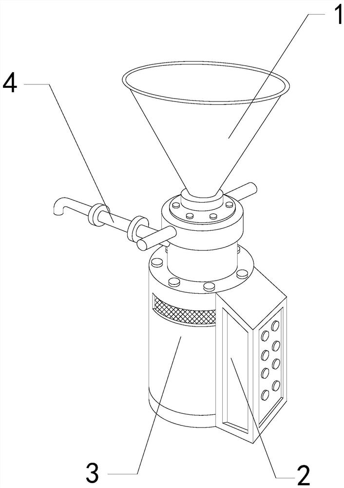
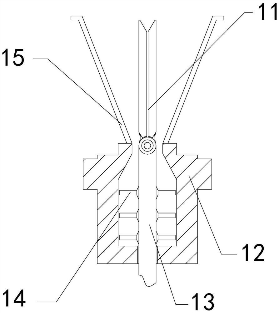
[0029] The invention provides a kind of processing equipment for oil cleaning agent for environmental protection equipment, its structure includes a feed hopper 1, a control electric box 2, a drive base 3, and an outer discharge pipe 4, the rear end of the control electric box 2 and the drive base 3 The surfaces are attached together, the outer discharge pipe 4 is connected to the rear end flange of the drive base 3, and the feed hopper 1 is embedded in the upper end of the drive base 3; the feed hopper 1 includes an outer swing plate 11, Bottom frame 12, rotating shaft 13, blades 14, frame body 15, the outer swing plate 11 is hinged to the top of the rotating shaft 13, the rotating shaft 13 runs through the inner position of the bottom frame 12, and the blades 14 are fixed on the top of the rotating shaft 13 The outer surface position, the frame body 15 is welded to the upper end position of the bottom frame 12 .

[0...

Embodiment 2

[0036] For example Figure 6 -example Figure 9 Shown:

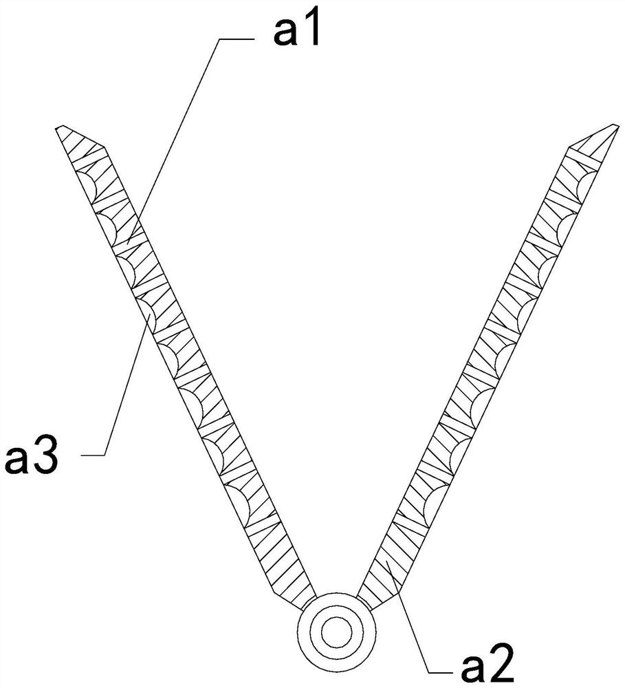
[0037]Wherein, the contact reduction groove a3 includes a rear plate c1, a middle slide plate c2, a pullback ring c3, ​​and an outer vibration block c4, the middle slide plate c2 is slidingly matched with the inside of the rear plate c1, and the pullback ring c3 is installed Between the inner side of the rear plate c1 and the rear end of the external vibration block c4, the rear end surface of the external vibration block c4 is connected to the front end of the middle slide plate c2, and the vibration generated by the mechanism swinging to the middle can make the outer The vibration block c4 slides outward along the rear plate c1 under the cooperation of the middle slide plate c2, so that the external vibration block c4 can generate an outward throwing force on the powder raw material attached to its surface.

[0038] Wherein, the external vibrating block c4 includes an elastic piece c41, a fixed rod c42, and an extern...


PUM


Abstract

Disclosed oil stain cleaning agent processing equipment for environmental protection equipment structurally comprises a feeding hopper, a control electric box, a driving base and a discharging pipe, the rear end of the control electric box is attached to the surface of the driving base, the discharging pipe is connected with a flange at the rear end of the driving base, and the feeding hopper is fixedly embedded in the upper end position of the driving base. Water between the two outer swing plates can be guided out through an inner cavity in a clearing mechanism, so that water flow can flush away powdery raw materials on the inner wall of a frame body and push a clearing brush to shake at the same time, and the powdery raw materials on the inner side of the frame body can be wetted and cleared away through the clearing brush; and when an outer vibration block extends outwards, the external connecting surfaces can extend outwards under the cooperation of elastic pieces and fixing rods through thrust generated between two external connecting surfaces by reverse airflow, so that the external connecting surfaces can scrape a mixture of powdery raw materials and equivalent water on the inner side of a rear plate.

Description

technical field [0001] The invention relates to the field of oil stain cleaning agent equipment, in particular to an oil stain cleaning agent processing equipment for environmental protection equipment. Background technique [0002] The oil cleaning agent blending machine for environmental protection equipment is mainly used for the raw material blending of oil cleaning agent for environmental protection equipment. The raw material powder of oil cleaning agent for environmental protection equipment is introduced into the oil cleaning agent blending machine for environmental protection equipment through the feeding hopper , and then add an appropriate amount of water for stirring and neutralization. Based on the above description, the inventors found that the existing oil cleaning agent processing equipment for environmental protection equipment mainly has the following deficiencies, for example: [0003] Since the oily cleaning agent for environmental protection equipment us...

Claims


Application Information

Patent Timeline
Patent Type & Authority Applications(China)
IPC IPC(8): B01F15/02
CPCB01F35/711B01F35/71731B01F35/79B01F2101/48
Inventor 姚杨
Owner 济南一诺润滑油有限公司
Learn More