Cleaning device for an optical sensor and sensor assembly

A technology of optical sensors and sensor components, applied in the direction of optical device exploration, optical components, cleaning methods and utensils, etc., can solve the problem that cleaning devices are not as good as manual cleaning

Active Publication Date: 2021-06-22
BOBST MEX SA
View PDF7 Cites 1 Cited by
  • Summary
  • Abstract
  • Description
  • Claims
  • Application Information

AI Technical Summary

Problems solved by technology

In terms of cleaning effect, these cleaning devices are still not as good as manual cleaning

Method used


Image

  • Cleaning device for an optical sensor and sensor assembly
  • Cleaning device for an optical sensor and sensor assembly
  • Cleaning device for an optical sensor and sensor assembly

Examples


Embodiment Construction

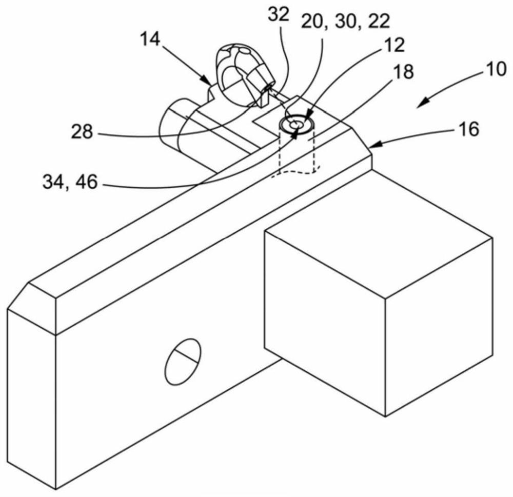
[0028] figure 1 A sensor assembly 10 is shown comprising an optical sensor 12 and a cleaning device 14 associated with the optical sensor 12 . Such sensor assemblies can be used in paper processing machines for detecting the presence of paper, for example in printing presses.

[0029] Both the optical sensor 12 and the cleaning device 14 are connected to a common support member 16 .

[0030] In the example shown, the optical sensor 12 includes an optical fiber 18 having an end face 20 . This end face 20 constitutes a sensing surface 22 of the optical sensor 12 .

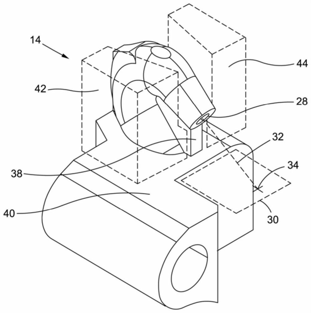
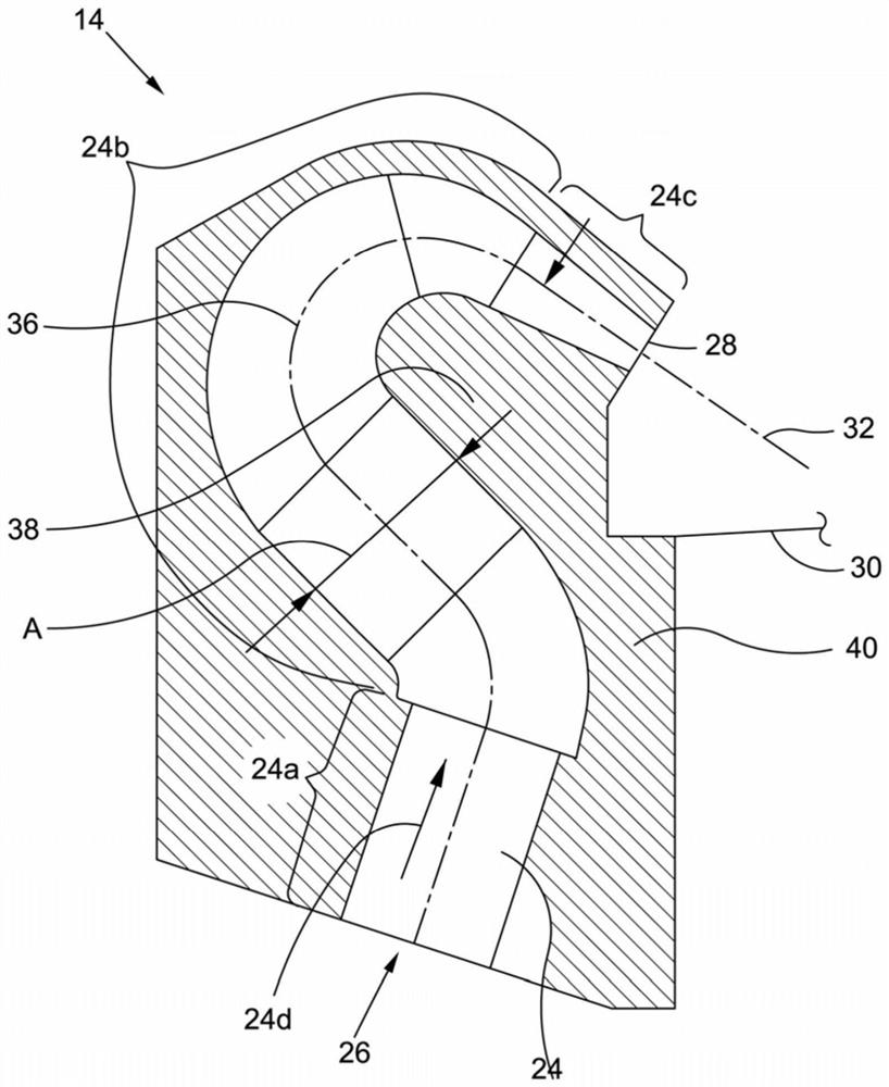
[0031] exist figure 2 and image 3 , the cleaning device 14 is shown in more detail. It includes a gas flow channel 24 having an inlet portion 24a, a middle portion 24b and an outlet portion 24c (see image 3 ).

[0032] The inlet portion 24a includes an inlet 26 to which air flow can be provided.

[0033] The outlet portion 24c includes an outlet 28 for discharging the airflow onto the target surface 30 of ...


PUM


Abstract

A cleaning device (14) for an optical sensor (12) is described. It comprises a gas flow channel oriented towards a target surface (30) such that a gas flowing through the gas flow channel is discharged onto the target surface (30). Additionally, an outlet (28) of the gas flow channel is facing the target surface (30) and a central axis (32) of the outlet intersects the target surface (30) substantially at a center (34) thereof and is oriented substantially at an angle of 30 to 70 degrees to the target surface (30). Furthermore, a sensor assembly (10) is presented which comprises an optical sensor (12) having a sensing surface (22) and a cleaning device (14) as described above.

Description

technical field [0001] The invention relates to a cleaning device for an optical sensor comprising a gas flow channel oriented towards a target surface such that gas flowing through the gas flow channel is expelled onto the target surface. [0002] The invention also relates to a sensor assembly comprising an optical sensor with a sensing surface and a cleaning device as described above. [0003] Such sensor assemblies and cleaning devices are known in the art. Background technique [0004] A well-known problem is that sensors, especially optical sensors, need to be kept clean for their reliable function, i.e. to ensure that the correct values ​​are captured by the sensor. This is the case for almost all types of sensors used in industrial environments, especially optical sensors for paper or cardboard converting machines. In such machines, optical sensors are used to detect the presence and / or correct position of the paper or cardboard to be processed. [0005] In this f...

Claims


Application Information

Patent Timeline
IPC IPC(8): B08B5/02G01V8/10
CPCB08B5/02G01V8/10G02B27/0006G01N21/15B08B17/02G01N2021/151
Inventor T·莱尔邱剑飞
Owner BOBST MEX SA
Why Eureka
Try Eureka