
Drilling machine for special-shaped workpiece

A technology for special-shaped workpieces and drilling machines, which is used in boring/drilling, drilling/drilling equipment, metal processing machinery parts, etc. problems, to achieve the effect of facilitating daily operation, improving fixing efficiency, and improving accuracy

Inactive Publication Date: 2021-06-22
李方东
View PDF0 Cites 4 Cited by
  • Summary
  • Abstract
  • Description
  • Claims
  • Application Information

AI Technical Summary

Problems solved by technology

[0003] When processing and drilling special-shaped workpieces, because the size and shape of each processed product are different, it is difficult for traditional fixtures to have a good fixing effect on the clamping of special-shaped workpieces, resulting in the processing of special-shaped workpieces. The difficulty of holes increases. Traditional processing of special-shaped workpieces generally requires positioning holes on the surface or other positions of the special-shaped workpieces, and then uses fixtures to fix the special-shaped workpieces according to the positions of the positioning holes. However, this method will destroy the special-shaped workpieces. Integrity makes it difficult to meet certain special requirements. Second, this method is more cumbersome to fix, and it is inconvenient to disassemble or clamp special-shaped workpieces, which is not conducive to the processing efficiency of the factory. Therefore, there is an urgent need for a fast and easy-to-fix Special-shaped workpiece drilling device that damages special-shaped workpieces

Method used


Image

  • Drilling machine for special-shaped workpiece
  • Drilling machine for special-shaped workpiece
  • Drilling machine for special-shaped workpiece

Examples


Embodiment Construction

[0038]The technical solutions in the embodiments of the present invention will be clearly and completely described below in conjunction with the embodiments of the present invention. Apparently, the described embodiments are only some of the embodiments of the present invention, not all of them. Based on the embodiments of the present invention, all other embodiments obtained by persons of ordinary skill in the art without creative efforts fall within the protection scope of the present invention.

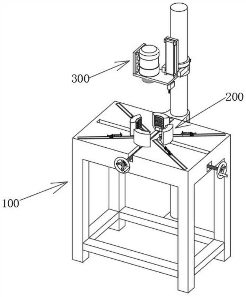
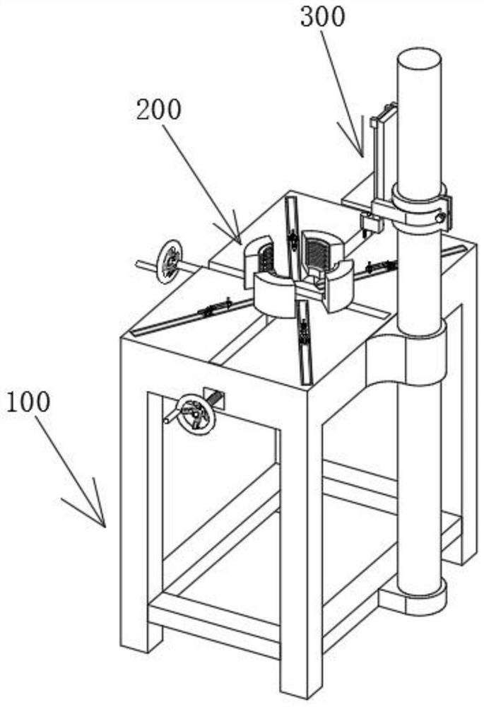
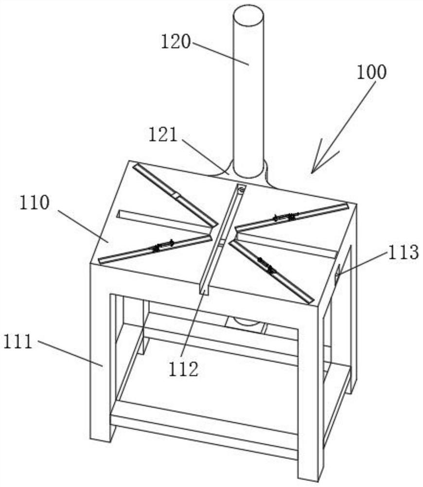
[0039] see Figure 1-15 As shown, a drilling machine for special-shaped workpieces includes a support mechanism 100, a clamping mechanism 200 and a movable drilling mechanism 300. The support mechanism 100 includes a support platform 110 and a support column 120. The four ends of the support platform 110 bottom surface The corners are fixedly connected with supporting legs 111, the middle part of the top surface of the support platform 110 is provided with a first rectangular groov...


PUM


Abstract

The invention relates to the technical field of drilling clamps, in particular to a drilling machine for a special-shaped workpiece. The drilling machine comprises a supporting mechanism, a clamping mechanism and a movable drilling mechanism, wherein the supporting mechanism comprises a supporting table and supporting columns, supporting legs are fixedly connected to the four end corners of the bottom face of the supporting table, a first rectangular groove is formed in the middle of the top face of the supporting table, a second rectangular groove is formed in the middle of one short side wall of the supporting table, and sliding grooves are formed in the top face of the supporting table by facing four diagonal lines with the middle of the supporting table serving as the center point. According to the drilling machine for the special-shaped workpiece, a first two-way lead screw and a second two-way lead screw are rotationally connected into the first rectangular groove and the second rectangular groove, a first connecting lug and a second connecting lug drive the clamp to clamp the special-shaped workpiece by rotating the first two-way lead screw and the second two-way lead screw, so that the surface of the special-shaped workpiece cannot be damaged, the whole fixing process is more time-saving and labor-saving, and the fixing efficiency of the special-shaped workpiece is greatly improved.

Description

technical field [0001] The invention relates to the technical field of drilling fixtures, in particular to a drilling machine for special-shaped workpieces. Background technique [0002] Most of the existing processed products can be divided into two categories: standard parts and non-standard parts. Standard parts are the same size, material and specification used under normal circumstances. Such products are usually in large quantities, and non-standard parts are Special-shaped workpieces, that is, the sizes, materials, and specifications used in special cases are different. Such products are usually made according to specific design drawings; [0003] When processing and drilling special-shaped workpieces, because the size and shape of each processed product are different, it is difficult for traditional fixtures to have a good fixing effect on the clamping of special-shaped workpieces, resulting in the processing of special-shaped workpieces. The difficulty of holes inc...

Claims


Application Information

Patent Timeline
Patent Type & Authority Applications(China)
IPC IPC(8): B23B41/00B23B47/00B23Q3/06
CPCB23B41/00B23B47/00B23Q3/062
Inventor 李方东
Owner 李方东
Learn More