Turning method for sputtering surface of rotary target material
A sputtering surface and rotating target technology, applied in the target field, can solve the problem that the sputtering performance of the target needs to be further improved, and achieve the effects of excellent sputtering performance, improved surface effect, and no residual stress.
- Summary
- Abstract
- Description
- Claims
- Application Information
AI Technical Summary
Problems solved by technology
Method used
Image
Examples
Embodiment 1
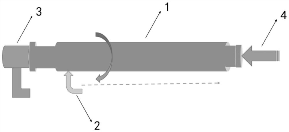
[0051] This embodiment provides a method for turning the sputtering surface of a rotating target, such as figure 1 As shown, first install one end of the rotating target 1 on the fixed bracket 3, and place the fixture thimble 4 on the other end of the rotating target 1; install the cutter 2, and keep the blade attached to the surface of the rotating target 1, The dotted line is the feed path of tool 2.
[0052] The turning method described in this embodiment includes rough turning, semi-finish turning, finish turning and polishing performed in sequence. The feed rate of the rough turning is 0.8mm, the spindle speed is 210rpm, and the feed rate is 0.25mm / min; the semi-finishing turning is divided into two steps, including the first semi-finishing turning and the second half-finishing in sequence. Finishing turning; the feed rate of the first semi-finishing turning is 0.4mm, the spindle speed is 340rpm, and the feed rate is 0.15mm / min; the feed rate of the second semi-finishing...
Embodiment 2
[0055] This embodiment provides a method for turning the sputtering surface of a rotating target, such as figure 1 As shown, first install one end of the rotating target 1 on the fixed bracket 3, and place the fixture thimble 4 on the other end of the rotating target 1; install the cutter 2, and keep the blade attached to the surface of the rotating target 1, The dotted line is the feed path of tool 2.
[0056] The turning method described in this embodiment includes rough turning, semi-finish turning, finish turning and polishing performed in sequence. The feed rate of the rough turning is 0.7mm, the spindle speed is 200rpm, and the feed rate is 0.25mm / min; the semi-finishing turning is divided into two steps, including the first semi-finishing turning and the second half-finishing in sequence. Finishing turning; the feed rate of the first semi-finishing turning is 0.35mm, the spindle speed is 300rpm, and the feed rate is 0.15mm / min; the feed rate of the second semi-finishin...
Embodiment 3
[0059] This embodiment provides a method for turning the sputtering surface of a rotating target, such as figure 1 As shown, first install one end of the rotating target 1 on the fixed bracket 3, and place the fixture thimble 4 on the other end of the rotating target 1; install the cutter 2, and keep the blade attached to the surface of the rotating target 1, The dotted line is the feed path of tool 2.
[0060] The turning method described in this embodiment includes rough turning, semi-finish turning, finish turning and polishing performed in sequence. The feed rate of the rough turning is 0.9mm, the spindle speed is 230rpm, and the feed rate is 0.25mm / min; the semi-finishing turning is divided into two steps, including the first semi-finishing turning and the second half-finishing in sequence. Finishing turning; the feed rate of the first semi-finishing turning is 0.45mm, the spindle speed is 370rpm, and the feed rate is 0.15mm / min; the feed rate of the second semi-finishin...
PUM
| Property | Measurement | Unit |
|---|---|---|
| Roughness | aaaaa | aaaaa |
Abstract
Description
Claims
Application Information
 - R&D Engineer
- R&D Manager
- IP Professional
- Industry Leading Data Capabilities
- Powerful AI technology
- Patent DNA Extraction
Browse by: Latest US Patents, China's latest patents, Technical Efficacy Thesaurus, Application Domain, Technology Topic, Popular Technical Reports.
© 2024 PatSnap. All rights reserved.Legal|Privacy policy|Modern Slavery Act Transparency Statement|Sitemap|About US| Contact US: help@patsnap.com


