Rapid rubber band cutting device for rubber band processing

A rubber band and fast technology, which is applied in metal processing and other directions, can solve the problem of single size of the cutting ring, and achieve the effect of easy replacement, convenient material removal, and improved work efficiency

Active Publication Date: 2021-06-22
安徽省潜山市创先实业有限公司
View PDF13 Cites 0 Cited by
  • Summary
  • Abstract
  • Description
  • Claims
  • Application Information

AI Technical Summary

Problems solved by technology

[0004] The purpose of the present invention is to solve the problem of the single size of the cutting ring in the prior art, and propose a fast ring cutting device for rubber band processing

Method used


Image

  • Rapid rubber band cutting device for rubber band processing
  • Rapid rubber band cutting device for rubber band processing
  • Rapid rubber band cutting device for rubber band processing

Examples


Embodiment 1

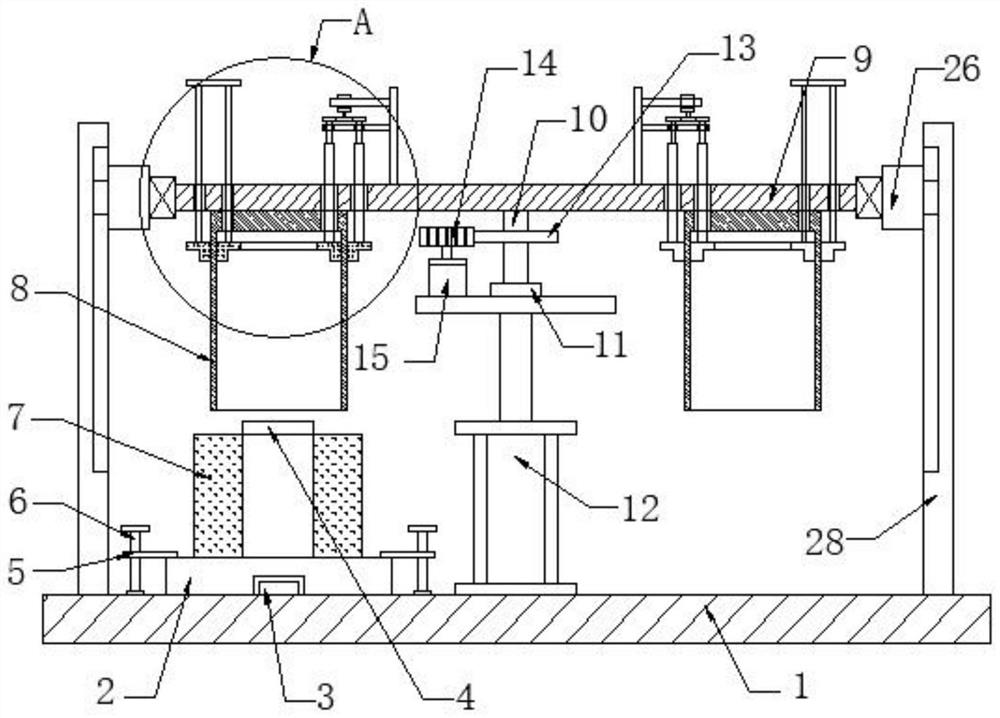
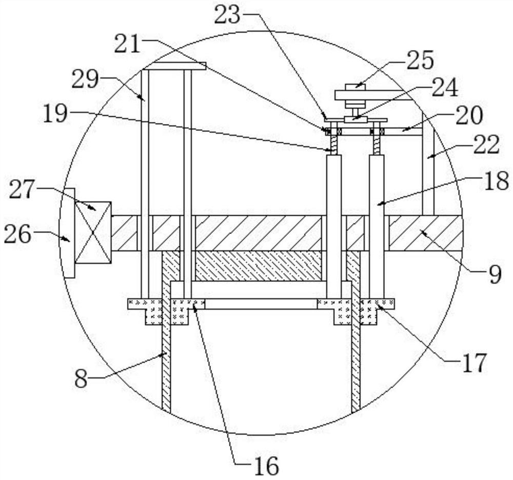
[0031] refer to Figure 1-5 , a fast loop cutting device for rubber band processing, comprising a base 1, a fixed seat 2 and a sleeve rod 4, the upper end of the base 1 is provided with a fixed seat 2 on the left side, and the upper end of the base 1 is provided with a positioning rod 3 corresponding to the fixed seat 2, and the positioning rod 3 Inserted on the fixed seat 2, the middle part of the upper end of the fixed seat 2 is provided with a sleeve rod 4, the left and right sides of the upper end of the fixed seat 2 are provided with a pressure plate 5, the lower end of the pressure plate 5 is fitted with the fixed seat 2, and the pressure plate 5 is provided with a rotating rod 6. The rotating rod 6 is rotated to connect the base 1. The sleeve rod 4 is covered with a cylindrical rubber 7. When the cylindrical rubber 7 needs to be replaced, the rotating rod 6 drives the pressure plate 5 to rotate, so that the pressure plate 5 is away from the fixed seat 2. Just pull out t...

Embodiment 2

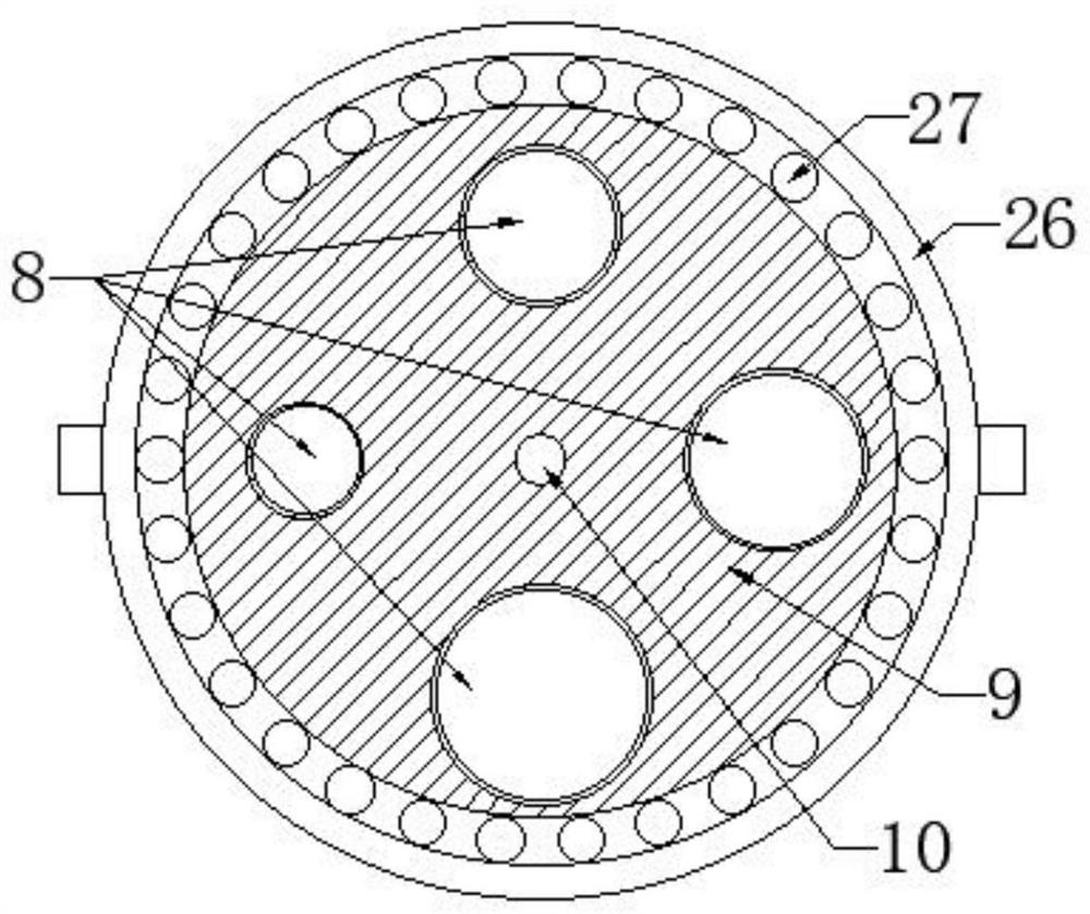
[0033] Such as Figure 1-5 As shown, this embodiment is basically the same as Embodiment 1. Preferably, a fixed sleeve 26 is provided on the outer side of the support plate 9, a bearing three 27 is provided at the connection between the support plate 9 and the fixed sleeve 26, and the support plate 9 is rotatably connected to the fixed sleeve 26. , the left and right ends of the fixed cover 26 are all provided with connecting plates 28, the lower ends of the connecting plates 28 are fixedly connected to the base 1, and one end of the connecting plates 28 close to each other is provided with a chute corresponding to the fixed cover 26, and the fixed cover 26 is slidably connected with the connecting plate 28, When the support plate 9 moves up and down to work, the connecting plate 28, the fixed sleeve 26 and the three bearings 27 provided play a stabilizing effect when the support plate 9 works.

[0034] The present invention facilitates cutting out rubber bands with different ...


PUM


Abstract

The invention discloses a rapid rubber band cutting device for rubber band processing. The rapid rubber band cutting device comprises a base, a fixing base and a sleeve rod, wherein the fixing base is arranged on the left side of the upper end of the base, the sleeve rod is arranged in the middle of the upper end of the fixing base, the sleeve rod is sleeved with cylindrical rubber, a plurality of rubber band cutting knives are arranged on the upper side of the sleeve rod, the inner diameter of each rubber band cutting knife is sequentially increased, a supporting plate is arranged at the upper ends of the rubber band cutting knives, a rotating shaft is arranged in the middle of the lower end of the supporting plate, a first bearing is arranged at the lower end of the rotating shaft, a hydraulic cylinder is arranged at the lower end of the first bearing, the lower end of the hydraulic cylinder is fixedly connected with the base, a first gear is arranged on the rotating shaft, the left end of the first gear is meshed with a second gear, and a first motor is arranged at the lower end of the second gear. According to the rapid rubber band cutting device, through mutual cooperation of all the components, rubber bands with different diameters can be conveniently cut out according to actual needs, the application range is wide, and therefore the working efficiency is improved, follow-up material taking is facilitated, a stabilizing effect is achieved when the supporting plate works, cylindrical rubber to be cut is conveniently replaced, operation is easy, and use is convenient.

Description

technical field [0001] The invention relates to the technical field of rubber band processing, in particular to a quick loop cutting device for rubber band processing. Background technique [0002] A rubber band is a short loop made of rubber and latex, generally used to tie things together, invented by Stephen Perry on March 17, 1845. The scientific name of the rubber band is latex rubber ring and latex tape. It is made of latex by dipping. It has the characteristics of high elongation, good resilience, low price and convenient use. Its manufacturing process includes dipping, vulcanization, demoulding, ring cutting (strip) and other processes. Mainly used for binding items. [0003] When the existing ring cutting device for rubber band processing is in use, it cannot cut the cylindrical rubber into rubber rings with different inner diameters according to actual needs, and can only produce rubber rings of the same size in a single way, so that the device is applicable Po...

Claims


Application Information

Patent Timeline
Patent Type & Authority Applications(China)
IPC IPC(8): B26D3/10B26D1/09B26D5/12B26D7/18B26D7/01
CPCB26D3/10B26D1/09B26D5/12B26D7/1818B26D7/01B26D2007/013
Inventor 杜传来余同江邹儒平
Owner 安徽省潜山市创先实业有限公司
Why Eureka
Try Eureka