A quick loop cutting device for rubber band processing

A rubber band, fast technology, applied in metal processing and other directions, can solve the problem of single size of cutting ring, and achieve the effect of easy replacement, wide application range, and convenient material retrieval.

Active Publication Date: 2022-06-24
安徽省潜山市创先实业有限公司
View PDF0 Cites 0 Cited by
  • Summary
  • Abstract
  • Description
  • Claims
  • Application Information

AI Technical Summary

Problems solved by technology

[0004] The purpose of the present invention is to solve the problem of the single size of the cutting ring in the prior art, and propose a fast ring cutting device for rubber band processing

Method used


Image

  • A quick loop cutting device for rubber band processing
  • A quick loop cutting device for rubber band processing
  • A quick loop cutting device for rubber band processing

Examples


Embodiment 1

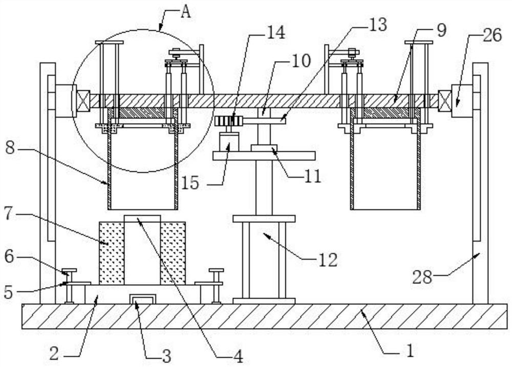
[0031] refer to Figure 1-5 , a quick cutting ring device for rubber band processing, including a base 1, a fixed seat 2 and a sleeve rod 4, the upper end of the base 1 is provided with a fixed seat 2 on the left side, the upper end of the base 1 is provided with a positioning rod 3 corresponding to the fixed seat 2, and the positioning rod 3 is inserted on the fixed seat 2, the upper end of the fixed seat 2 is provided with a sleeve rod 4, and the left and right sides of the upper end of the fixed seat 2 are provided with pressure plates 5. 6. The rotating rod 6 is rotated to connect the base 1, and the sleeve rod 4 is sleeved with a cylindrical rubber 7. When the cylindrical rubber 7 needs to be replaced, the rotating rod 6 drives the pressure plate 5 to rotate, so that the pressure plate 5 is away from the fixed seat 2. The fixing seat 2 can be directly pulled out from the positioning rod 3, which is convenient to replace the cylindrical rubber 7 to be cut. The inner diame...

Embodiment 2

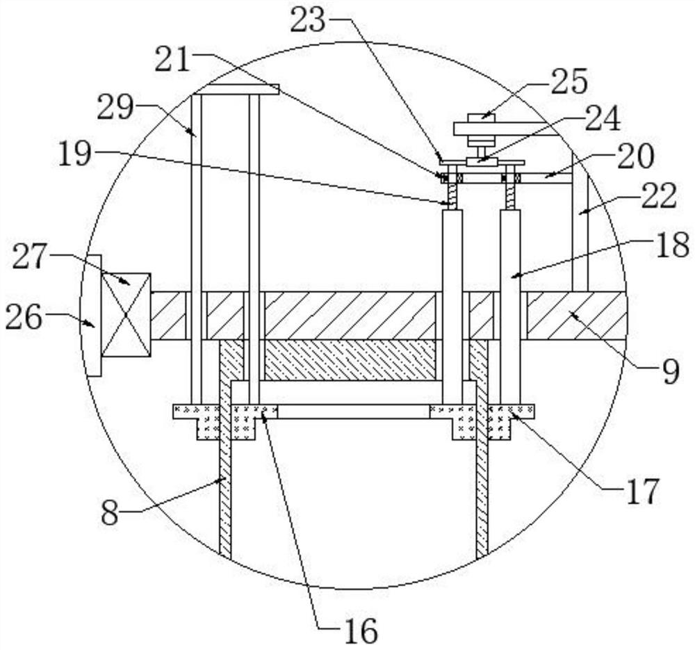
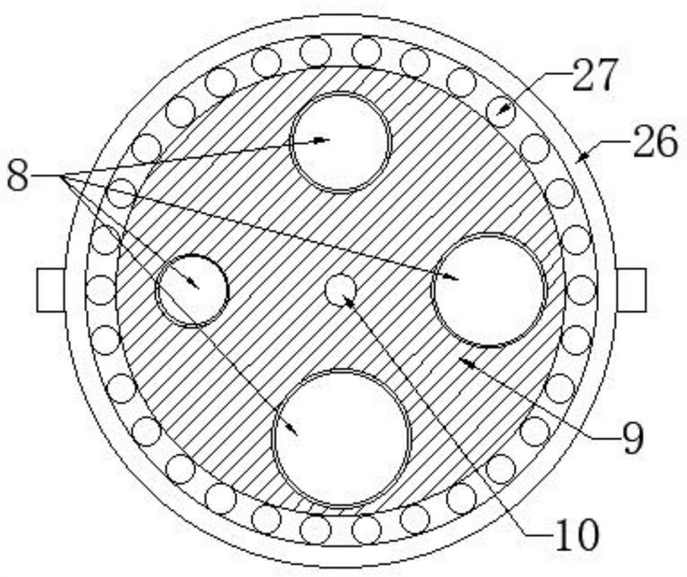
[0033] like Figure 1-5 As shown, this embodiment is basically the same as Embodiment 1. Preferably, a fixing sleeve 26 is provided on the outer side of the support plate 9, a bearing 3 27 is provided at the connection between the support plate 9 and the fixing sleeve 26, and the support plate 9 is rotatably connected to the fixing sleeve 26. , the left and right ends of the fixed sleeve 26 are provided with connecting plates 28, the lower end of the connecting plate 28 is fixed to the connection base 1, the end of the connecting plates 28 that are close to each other is provided with a chute corresponding to the fixed sleeve 26, and the fixed sleeve 26 is slidably connected with the connecting plate 28, When the support plate 9 moves up and down to work, the provided connecting plate 28 , the fixed sleeve 26 and the bearing 3 27 play a stable role for the support plate 9 to work.

[0034] Through the mutual cooperation between the various components, the invention is convenie...


PUM


Abstract

The invention discloses a fast loop cutting device for rubber band processing, which comprises a base, a fixing seat and a sleeve rod. Cylindrical rubber, a number of ring cutting knives are arranged on the upper side of the sleeve rod, and the inner diameter of each ring cutting knife increases sequentially, a support plate is provided at the upper end of the ring cutting knife, a rotating shaft is provided at the middle of the lower end of the supporting plate, and a bearing is provided at the lower end of the rotating shaft The lower end of the bearing is provided with a hydraulic cylinder, the lower end of the hydraulic cylinder is fixedly connected to the base, the rotating shaft is provided with a gear 1, the left end of the gear 1 meshes with a gear 2, and the lower end of the gear 2 is provided with a motor 1. The present invention facilitates the cutting of rubber bands with different diameters according to actual needs through the mutual cooperation between the various parts, and has a wide application range, thereby improving work efficiency, facilitating subsequent material retrieving, and playing a role in the work of the support plate. Stable function, easy to replace the cylindrical rubber to be cut, easy to operate and easy to use.

Description

technical field [0001] The invention relates to the technical field of rubber band processing, in particular to a quick ring cutting device for rubber band processing. Background technique [0002] A rubber band is a short loop made of rubber and latex, generally used to tie things together. It was invented by Stephen Perry on March 17, 1845. The scientific name of rubber band is rubber latex ring and rubber latex belt. It is made of latex by dipping method. It has the characteristics of high elongation, good resilience, low price and convenient use. The manufacturing process includes dipping, vulcanization, demoulding, ring cutting (strip) and other processes. Mainly used for bundling items. [0003] When the existing cutting ring device for rubber band processing is used, it is not possible to cut the cylindrical rubber into rubber rings of different inner diameters according to actual needs, and can only produce rubber rings of the same size alone, thus making the devi...

Claims


Application Information

Patent Timeline
Patent Type & Authority Patents(China)
IPC IPC(8): B26D3/10B26D1/09B26D5/12B26D7/18B26D7/01
CPCB26D3/10B26D1/09B26D5/12B26D7/1818B26D7/01B26D2007/013
Inventor 杜传来余同江邹儒平
Owner 安徽省潜山市创先实业有限公司
Why Eureka
Try Eureka