

Steel structure beam column
A steel structure, beam-column technology, applied in the field of steel structure beam-column, can solve problems such as damage to the connection between steel beam and steel column, reduce the service life of nodes, and align threaded holes with steel column threaded holes, so as to achieve convenient and Rapid, increase construction speed, increase the effect of strength
- Summary
- Abstract
- Description
- Claims
- Application Information
AI Technical Summary
Problems solved by technology
Method used
Image


Examples
Embodiment Construction
[0025] The following examples are for illustrative purposes only and are not intended to limit the scope of the invention.
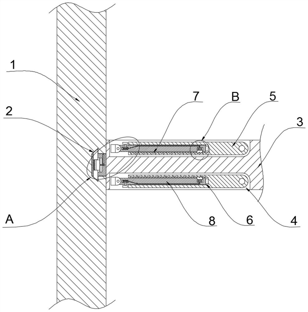
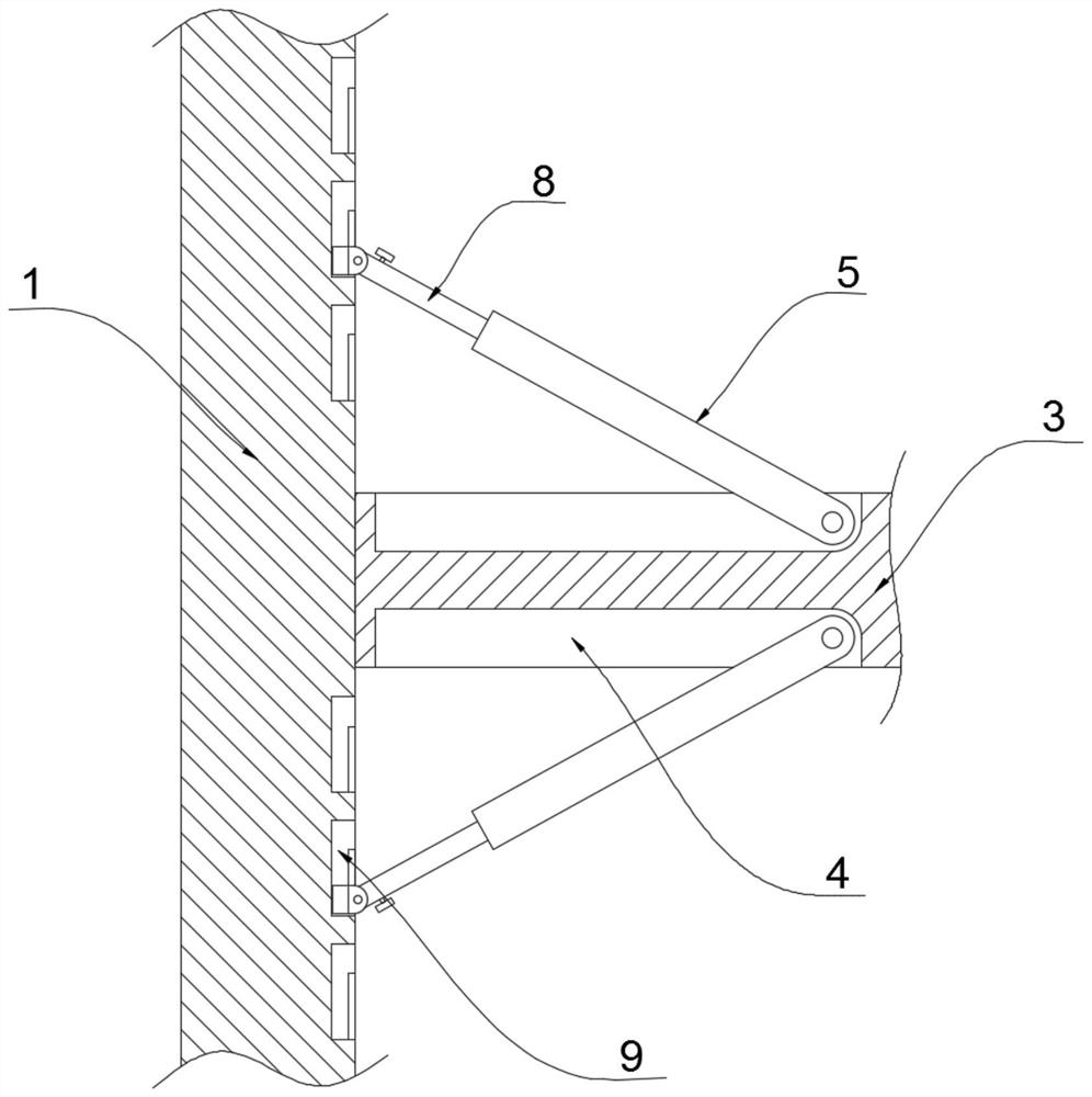
[0026] refer to Figure 1-6 , a beam column of steel structure, comprising a column 1, a groove 2 is opened inside the column 1, a beam 3 is connected to the column 1 through the groove 2, and a rotating groove 4 is symmetrically opened on both sides of the beam 3, and the inside of the rotating groove 4 is passed through a pin Rotationally connected with a support rod 5, the inside of the support rod 5 is provided with a chute 6, the inside of the chute 6 is slidably connected with an extension rod 8, the extension rod 8 runs through the chute 6, and the end of the extension rod 8 located outside the support rod 5 passes through The pin shaft is rotatably connected with a movable seat 10, the bottom of the movable seat 10 is welded and fixed with a base 11, the top of the beam 3 is welded and fixed with a connecting block 12, the support rod 5 and the e...
PUM
 Abstract
Description
Claims
Application Information