
Quick opening and closing gate valve

A closed and fast technology, applied in the direction of sliding valve, valve details, valve device, etc., can solve the problems of large cylinder diameter, unchanged stroke, waste, etc., to reduce the number of rotations, shorten the valve stem stroke, and save starting. closed time effect

Pending Publication Date: 2021-06-22
黑龙江省穆棱市电站阀门有限责任公司
View PDF6 Cites 0 Cited by
  • Summary
  • Abstract
  • Description
  • Claims
  • Application Information

AI Technical Summary

Problems solved by technology

If fast opening and closing is required, the existing product is to replace the electric actuator with a pneumatic actuator, which can increase the opening and closing speed, but the stroke remains unchanged. Due to the high medium pressure and the large friction of the valve stem, the pneumatic device requires a large cylinder diameter. , the air source requirements are also high, resulting in waste

Method used

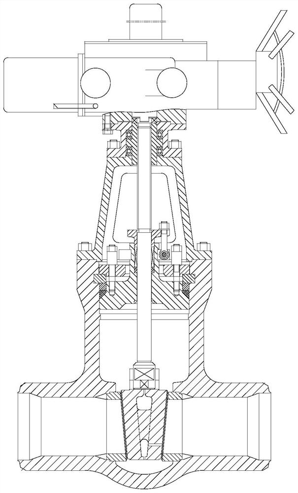
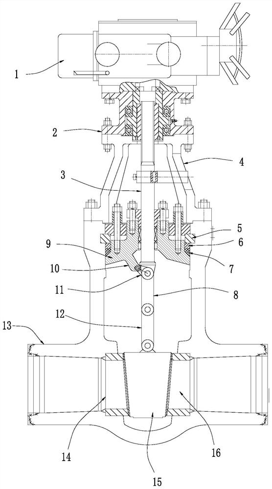
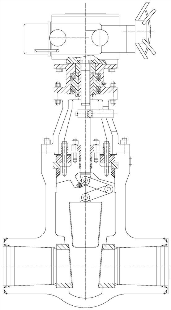

Image

  • Quick opening and closing gate valve
  • Quick opening and closing gate valve
  • Quick opening and closing gate valve

Examples


Embodiment

[0021] like Figure 2-3 As shown, a fast opening and closing gate valve includes a valve body 13, a valve seat 14, a packing chamber seat 9, a valve cover 4, a transition mounting seat 2, an electric actuator 1, a valve stem 3, and a valve disc 15. The valve seat 14 is located in the valve body 13, on which there is a flow groove 16 for medium circulation, the stuffing chamber seat 9 is detachably installed on the upper end of the valve body 13, the valve cover 4 is installed on the valve body 13, The transition mounting seat 2 is installed on the upper end of the valve cover 4, the electric actuator 1 is placed on the transition mounting seat 2, the valve stem 3 is drivingly connected with the electric actuator 1, and its sliding fit penetrates the stuffing chamber The seat 9 is connected with the valve disc 15. The electric actuator 1 drives the valve rod 3 to move up and down, and then drives the valve disc 15 to move up and down. The valve seat 14 is provided with a lockin...


PUM


Abstract

The invention discloses a quick opening and closing gate valve which comprises a valve body, a valve seat, a filler chamber seat, a valve cover, a transition mounting seat, an electric actuator, a valve rod, a valve clack, a circulation groove, a locking groove and a protruding part. A swing arm is hinged onto the protruding part and comprises a short arm and a long arm; the common end of the short arm and the long arm is hinged to the lower end of the valve rod; one end, away from the long arm, of the short arm is hinged with the protruding part; a hinge rod is hinged to the end, away from the valve rod, of the long arm; and the end, away from the long arm, of the hinge rod is hinged to the top of the valve clack. By means of the lever principle, when the maximum torque is needed at the moment of opening and closing, the force of the valve rod is completely used for opening and closing, after the valve clack is opened, a lever intervenes in work, the valve clack is pried to conduct the large stroke through the short stroke of the valve rod, and the purposes that under the condition that the torque of the actuator is not changed, the number of rotation turns is reduced, the stroke of the valve rod is shortened, and opening-closing time is saved are achieved.

Description

technical field [0001] The invention relates to the technical field of gate valves, in particular to a fast opening and closing gate valve. Background technique [0002] The gate valve is a gate of the opening and closing part. The direction of movement of the gate is perpendicular to the direction of the fluid. The gate valve can only be fully opened and fully closed, and cannot be adjusted or throttled. The gate valve is sealed by the contact between the valve seat and the gate plate. Usually, the sealing surface will be surfacing with metal materials to increase wear resistance, such as surfacing welding 1Cr13, STL6, stainless steel, etc. There are rigid gate valves and elastic gate valves. According to the different gate valves, gate valves are divided into rigid gate valves and elastic gate valves. [0003] Power station valves usually have high pressure, and it is rare to use pneumatic structure gate valves, especially for high-pressure and large-caliber pneumatic val...

Claims


Application Information

Patent Timeline
IPC IPC(8): F16K31/04F16K31/44F16K31/72F16K3/12F16K3/314F16K27/04F16K27/08F16H21/44
CPCF16K31/047F16K31/44F16K3/12F16K3/314F16K27/047F16K27/08F16H21/44
Inventor 刘德鑫
Owner 黑龙江省穆棱市电站阀门有限责任公司
Learn More